
Motorcycle bottom fork

A technology for motorcycles and flat forks, applied in bicycle accessories, axle suspension devices, transportation and packaging, etc., can solve the problems of poor driving comfort, high requirements on coaxiality, and insignificant adjustment effects, so as to improve the Driving comfort, improved comfort and long service life

Inactive Publication Date: 2009-01-21
LONCIN MOTOR
View PDF1 Cites 6 Cited by
  • Summary
  • Abstract
  • Description
  • Claims
  • Application Information

AI Technical Summary

Problems solved by technology

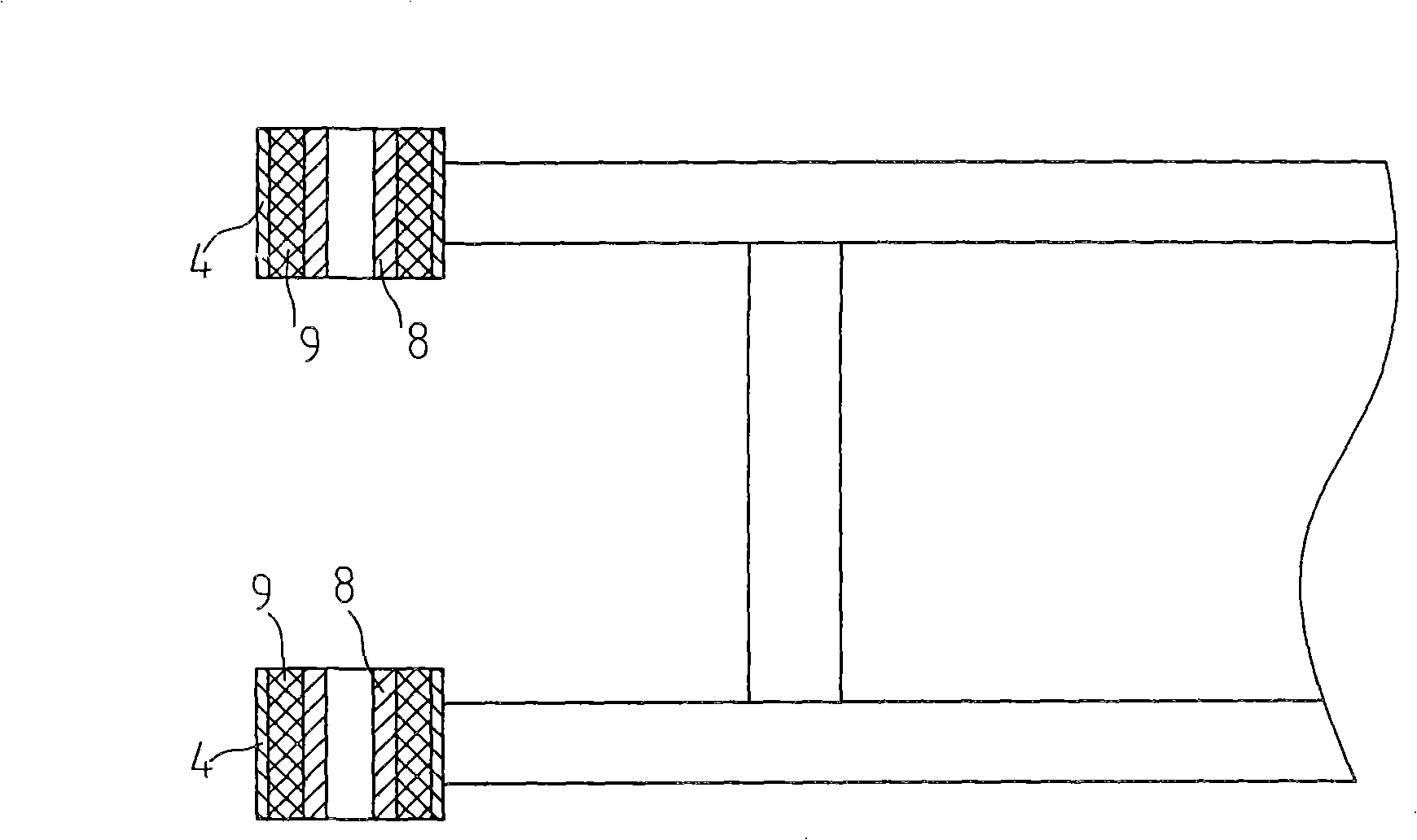
In order to reduce the vibration of the whole vehicle and improve the driving comfort, a shock absorbing sleeve is usually arranged in the casing 4 connected to the front end of the fork of the existing motorcycle and the large frame of the motorcycle, such as figure 1 As shown, the shock absorbing sleeve is composed of a liner 8 and a buffer rubber sleeve 9 set on the liner. When assembling, the shock absorbing sleeve is pressed into the sleeve 4 at the front end of the flat fork. The coaxiality requirement is relatively high, and there is sliding friction between the liner 8 and the connecting shaft, which results in fast wear and short service life;
[0003] The Chinese utility model patent No. 200420028795.9 provides a motorcycle rear flat fork, which is to be provided with two rolling bearings in the left and right sleeve holes where the front end is connected with the big frame of the car, although this structure can reduce the flat fork. The friction of the connecting shaft between the front end of the fork and the frame of the truck helps to improve the service life, but since the rolling bearing only provides the degree of freedom in the direction of rotation, the adjustment effect on the coaxiality error between the left and right sets of holes is not obvious. If the coaxiality error between the left and right sets of holes is large due to manufacturing or assembly reasons, there will also be problems of poor driving comfort and short service life of the flat fork

Method used


Image

  • Motorcycle bottom fork
  • Motorcycle bottom fork

Examples


Embodiment Construction

[0011] Below in conjunction with accompanying drawing and embodiment the present invention will be further described:

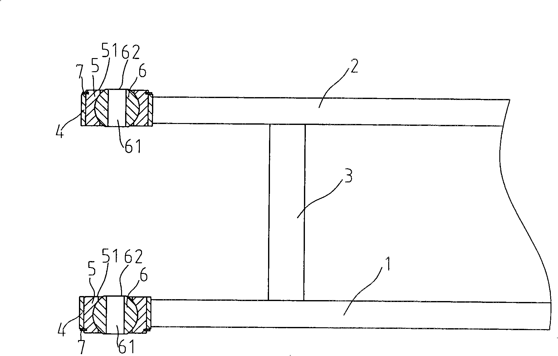
[0012] Such as figure 2 The flat fork of the motorcycle shown has a left frame bar 1, a right frame bar 2 and a connecting rod 3, and the connecting rod 3 is connected between the left frame bar 1 and the right frame bar 2 to form an H shape, and the left and right frame bars 1 and The front end of 2 is provided with a bushing 4 used to realize shaft connection with the large frame of the car. A spherical bearing is installed in the bushing 4. The spherical bearing is composed of a ball sleeve 5 and a steel ball 6 limited in the ball sleeve. , The steel ball 6 has a central shaft hole 61 .

[0013] When assembling, the spherical bearing is axially pressed into the sleeve 4, and the connecting shaft between the flat fork and the large frame passes through the central shaft hole of the steel ball 6, and the connecting shaft and the steel ball 6 are relatively...


PUM


Abstract

The invention provides a motorcycle bottom fork, comprising a left frame rod, a right frame rod and a connecting rod which is arranged between the left frame rod and the right frame rod; the front ends of the left frame rod and the right frame rod are respectively provided with a sleeve used for realizing the axial connection between motorcycle frames; the motorcycle bottom fork is characterized in that the sleeve is internally provided with a ball bearing which consists of a ball sleeve and a steel ball with the position limited in the ball sleeve; the steel ball is provided with a central shaft hole. The motorcycle bottom fork improves the driving comfortableness of the whole motorcycle, has long service life, and suitably reduces the coaxiality requirement of the left sleeve and the right sleeve which are arranged at the front end of the bottom fork, thus being beneficial to reducing the manufacture cost.

Description

technical field [0001] The invention relates to motorcycle parts, in particular to a motorcycle flat fork. Background technique [0002] The flat fork is one of the important parts of the motorcycle. It is installed between the frame and the wheel axle at the rear lower part of the motorcycle, and plays a role of supporting connection. In order to reduce the vibration of the whole vehicle and improve the driving comfort, a shock absorbing sleeve is usually arranged in the casing 4 connected to the front end of the fork of the existing motorcycle and the large frame of the motorcycle, such as figure 1 As shown, the shock absorbing sleeve is composed of a liner 8 and a buffer rubber sleeve 9 set on the liner. When assembling, the shock absorbing sleeve is pressed into the sleeve 4 at the front end of the flat fork. The coaxiality requirement is relatively high, and there is sliding friction between the liner 8 and the connecting shaft, which results in fast wear and short ser...

Claims


Application Information

Patent Timeline
Patent Type & Authority Applications(China)
IPC IPC(8): B62K25/04
Inventor 苟孝贵
Owner LONCIN MOTOR
Learn More