Floating type equipment for enclasping spindle nose

A floating, equipment technology, applied in metal processing equipment, metal rolling, metal rolling stands, etc., can solve the problems of affecting the speed of roll changing, inconvenient roll changing, etc., and achieve simple structure, convenient maintenance, and quick change Roller effect

Inactive Publication Date: 2009-01-28
CHINA NAT HEAVY MACHINERY RES INSTCO
View PDF0 Cites 2 Cited by
  • Summary
  • Abstract
  • Description
  • Claims
  • Application Information

AI Technical Summary

Problems solved by technology

[0002] In the field of metallurgical equipment, especially in the roll change of hot rolling mills, when changing rolls in a two-roll hot rolling mill, the vertical position of the roll head changes due to wear and tear on the universal joint shaft rolling mill end shaft head. , so that the roll shaft head and the joint end of the universal joint shaft are in different positions, which will cause problems such as inconvenient roll change and affect the speed of roll change

Method used


Image

  • Floating type equipment for enclasping spindle nose

Examples


Embodiment Construction

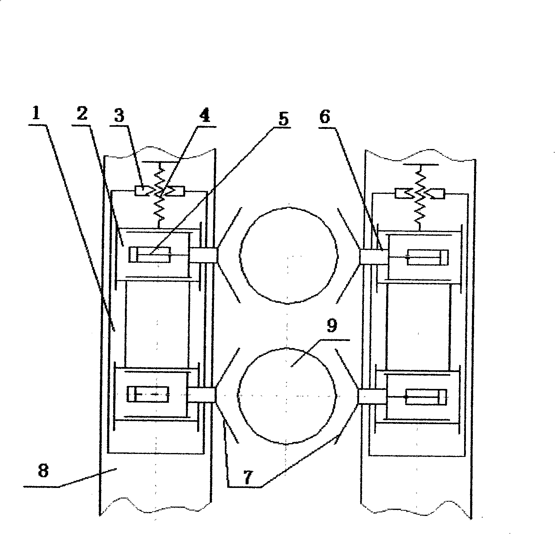
[0010] Such as figure 1 As shown: the vertical sliding guide rail 1 is fixed on the left and right sides of the transmission window of the rolling mill stand 8, and there are two vertically moving sliders and the horizontal guide rail 2 on the vertical sliding guide rail 1; the upper end of the vertical sliding guide rail 1 is fixed with a lifting nut 3; The lower end of the lifting screw 4 is fixed on the vertical moving slider and the horizontal guide rail 2; the lifting nut 3 is connected with the lifting screw 4; the lifting screw 4 moves up and down along the lifting nut 3 to drive two vertical moving sliders and the horizontal guide rail 2 Move up and down; the vertical moving slider and the horizontal guide rail 2 are respectively connected with the holding cylinder 5, the piston rod 6 is connected with the holding V-shaped block 7, and the piston rod 6, the holding V-shaped block 7, the vertical moving slider and the horizontal The clamping mechanism formed by the guid...


PUM


Abstract

The invention belongs to the field of metallurgical equipment, and in particular relates to a floating type spindle head clasping device for a hot rolling mill assembly to realize quick roll changing. The device is characterized in that a vertical slide rail (1) is fixed on the two sides of a driving window of a rolling mill housing (8), the two sides of the vertical slide rail (1) are respectively provided with vertical moving slide blocks and a horizontal slide rail (2); a lifting nut (3) is fixed on the upper end of the vertical slide rail (1); the lower end of a lifting screw (4) is fixed on the vertical moving slide blocks and the horizontal slide rail (2); the lifting nut (3) is connected with the lifting screw (4); the lifting screw (4) moves up and down along the lifting nut (3) to drive the two vertical moving slide blocks and the horizontal slide rail (2) to move up and down; the vertical moving slide blocks at the two sides and the horizontal slide rail (2) are respectively connected with a clasping oil cylinder (5), and a piston rod (6) is connected with a clasping V-shaped block (7). The floating type spindle head clasping device has the advantages of simple structure, safe and reliable performance, which can realize quick roll changing.

Description

technical field [0001] The invention belongs to the field of metallurgical equipment, in particular to a floating shaft head clamping equipment for a hot rolling mill to realize rapid roll change. Background technique [0002] In the field of metallurgical equipment, especially in the roll change of hot rolling mills, when changing rolls in two-roll hot rolling mills, the vertical position of the roll shaft head changes due to wear and tear of the rolling mill end shaft head of the universal joint shaft. , so that the roll shaft head and the joint end of the universal joint shaft are in different positions, which leads to problems such as inconvenient roll change and affecting roll change speed. Contents of the invention [0003] The object of the present invention is to provide a floating type shaft head clamping device with simple structure, safe and reliable performance and fast roll changing method for hot rolling mill. [0004] The technical solution of the present i...

Claims


Application Information

Patent Timeline
Patent Type & Authority Applications(China)
IPC IPC(8): B21B31/08
Inventor 张凯
Owner CHINA NAT HEAVY MACHINERY RES INSTCO
Why Eureka
Try Eureka