Clamping device

A clamping device and clamping tool technology, used in positioning devices, clamping, accessories of tool holders, etc., can solve problems such as imbalance, leakage, accumulation of debris in the shock-absorbing cavity, etc., to prevent leakage. Effect

Active Publication Date: 2010-08-25
SCHUNK GMBH & CO KG
View PDF3 Cites 0 Cited by
  • Summary
  • Abstract
  • Description
  • Claims
  • Application Information

AI Technical Summary

Problems solved by technology

[0006] But the disadvantage is that debris and the like can accumulate in the shock absorbing cavity
Due to the uneven formation of such debris accumulation in the damping cavity, an unavoidable imbalance occurs, which is a defect for parts of the machine tool at very high speeds
[0007] A further disadvantage is that when using tools with an internal coolant supply, especially with clamping mechanisms that work according to the applicant's friction technology, cooling liquid can pass through the gap formed between the receptacle and the clamped tool. Gap, reaching the end face on the workpiece side of the clamping device and leaking

Method used


Image

  • Clamping device
  • Clamping device
  • Clamping device

Examples


Embodiment Construction

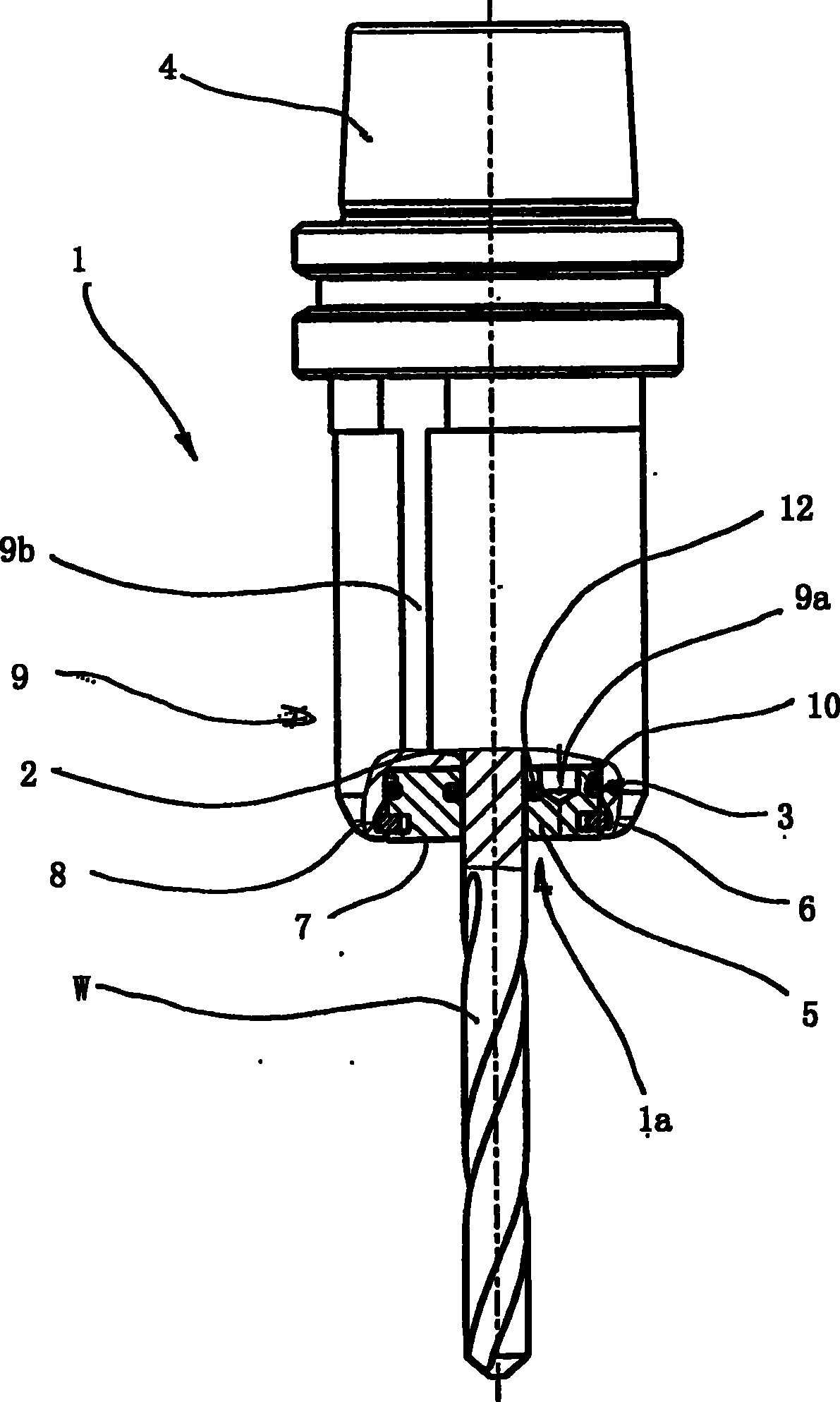
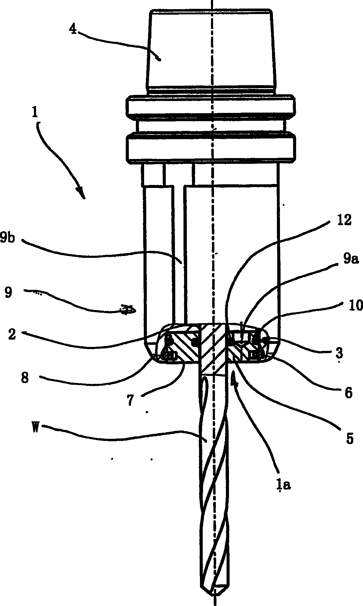
[0024] FIG. 1 shows a specific embodiment of a clamping device according to the invention for clamping a tool, which is designed here as a clamping chuck, but can also be integrated, for example, directly into the work spindle of a machine tool. The clamping chuck comprises a base body 1 made of a dimensionally stable material, such as steel, which has a central receptacle 2 at its end for a tool W to be clamped, here a core drill, of Cylindrical handle. At its other end, the base body 1 has, in a known manner, an interface 4 for clamping into a working spindle of a machine tool.

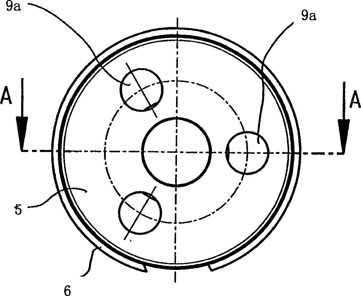
[0025] An annular space 3 is provided in the base body 1 , which surrounds the front region of the receptacle 2 and is open towards the tool-side end face 1 a of the base body and towards the receptacle 2 . The annular cover 5 is inserted into the annular space 3 and is secured axially by a locking ring 6 which engages in corresponding annular grooves 7 , 8 in the outer wall of the cover 5 and in t...


PUM


Abstract

The invention relates to a clamping device for clamping tools, with a receptacle (2) encircled by an annular space (3). The annular space (3) is open towards the tool-side face (1a) of the chuck body (1) and towards the receptacle (2) and is closed by a cover (5). On the receptacle side of the inside wall of the cover (5), there is an annular groove (13) in which there is a gasket (12), wherein aliquid can be fed to the annular groove (13) to press the gasket (12) inserted in the annular groove inward and thus to seal off actively a gap formed between the cover (5) and a tool (W) inserted inthe receptacle (2).

Description

technical field [0001] The invention relates to a clamping device for clamping a tool, having a base body in which a central housing is formed for the shank of the tool to be clamped; and an annular ring formed around the housing The space, wherein the annular space is open towards the workpiece-side end face of the chuck body and towards the receptacle. Background technique [0002] A clamping device of this type is known, for example, from WO 00 / 76703 and is used for fastening a tool holder, for example a drill holder, or a mill holder, to a working spindle of a corresponding machine tool. They are used especially for clamping small tools. [0003] In the clamping device disclosed by document WO 00 / 76703, the tool is to be clamped by a shrink fit. Furthermore, the device usually consists of a base body made of metal, which has a central receptacle for the shank of the tool to be clamped. The diameter of the receptacle is measured in such a way that it is slightly smalle...

Claims


Application Information

Patent Timeline
Patent Type & Authority Patents(China)
IPC IPC(8): B23B31/00
CPCB23B2226/33B23B2250/16B23B2260/126B23B2231/24B23B31/001Y10T279/17615
Inventor 拉尔夫·彼得
Owner SCHUNK GMBH & CO KG
Why Eureka
Try Eureka