Food waste disposer clean-out mechanism

A technology for food waste treatment and components, used in grain processing, construction, water supply installations, etc., can solve problems such as insufficient flushing, odor generation, and reduced grinding performance

Active Publication Date: 2009-01-28
EMERSON ELECTRIC CO
View PDF0 Cites 3 Cited by
  • Summary
  • Abstract
  • Description
  • Claims
  • Application Information

AI Technical Summary

Problems solved by technology

But inadequate flushing can cause food clogging and foul odors
If the water flow channel in

Method used


Image

  • Food waste disposer clean-out mechanism
  • Food waste disposer clean-out mechanism
  • Food waste disposer clean-out mechanism

Examples


Embodiment Construction

[0024] Illustrative embodiments of the invention are described below. In the interest of clarity, this specification does not describe all features of an actual implementation. It should of course be understood that during the development of any actual embodiment, many implementation-specific decisions are made to achieve the developer's specific goals, such as compliance with system-related and business-related constraints, which vary from implementation to implementation. Furthermore, it should be understood that such a development effort might be complex and time consuming, but would nevertheless be a routine undertaking for those of ordinary skill in the art having the benefit of the present invention.

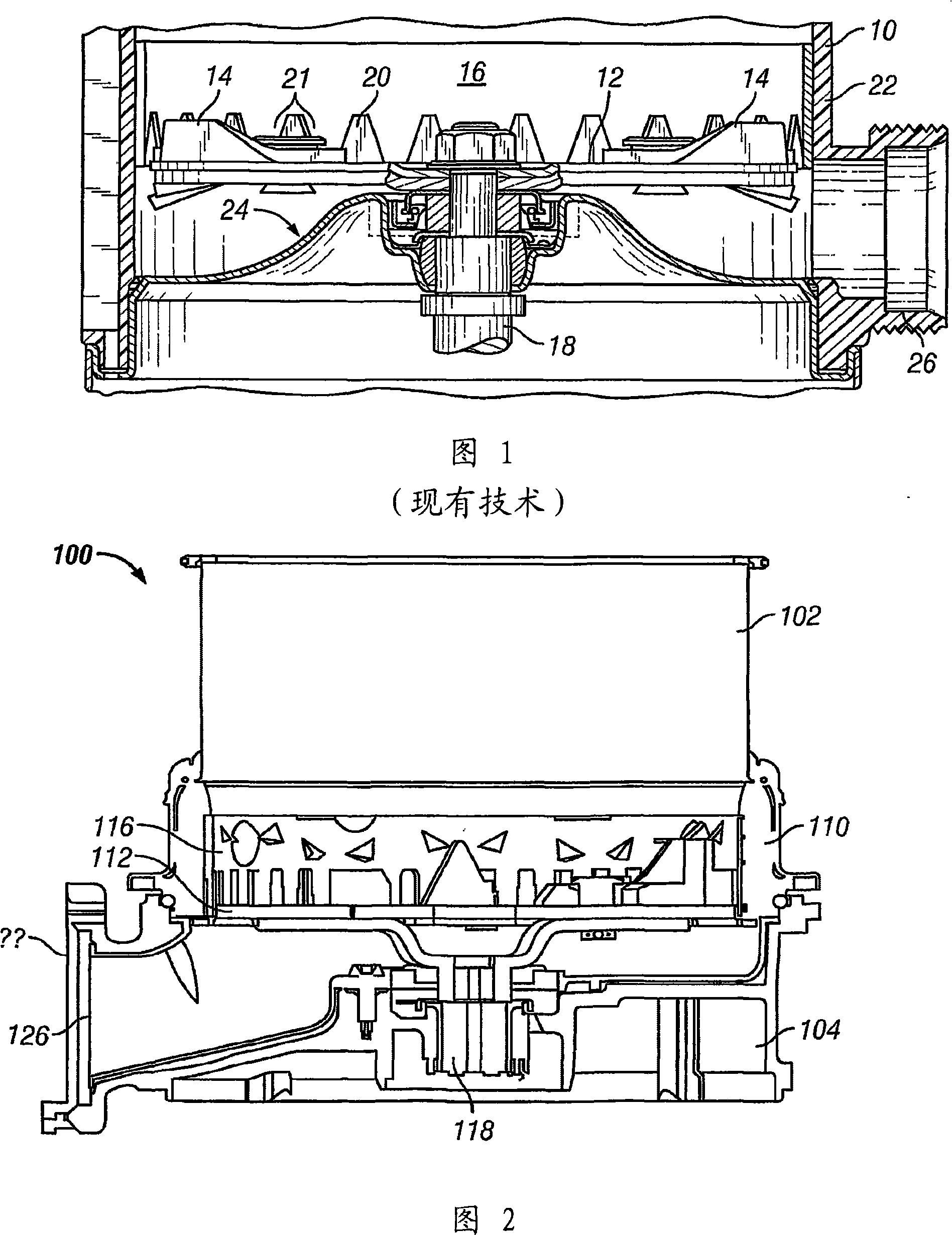
[0025] Figure 2 shows portions of an exemplary food waste disposer in accordance with the teachings of the present invention. The food waste disposer 100 includes a food conveying part 102 and a grinding mechanism 110 disposed between the food conveying part 102 and a mot...


PUM


Abstract

A shredder plate assembly for a food waste disposer includes a disk with one or more water slinging devices attached, so that water flowing into the disposer flows over the water slinging device and against the inside of the disposer housing as the disk rotates.

Description

[0001] Cross References to Related Applications [0002] This application claims the benefit of and priority to US Patent Application No. 11 / 164,976, filed December 13, 2005 (13 / 12 / 2005), which is incorporated herein by reference. technical field [0003] The present invention relates generally to food waste disposers. Background technique [0004] Food waste disposers are used to break up food waste into particles small enough to pass safely down household drains. A traditional processor includes a food conveying part, a motor part and a grinding mechanism arranged between the food conveying part and the motor part. The food delivery portion includes a housing forming an inlet for receiving food waste and water. The food delivery section delivers food waste to the grinding mechanism, and the motor section includes a motor that transmits rotational motion to a motor shaft to operate the grinding mechanism. [0005] Typically, the grinding mechanism for comminution consist...

Claims


Application Information

Patent Timeline
IPC IPC(8): E03C1/266B02C18/00
CPCE03C1/2665B02C18/18
Inventor 斯科特·W·安德森约瑟夫·G·法梅里尼古拉斯·J·赫希史蒂文·P·汉森辛西娅·C·雅拉-阿尔蒙特理查德·琼克
Owner EMERSON ELECTRIC CO
Why Eureka
Try Eureka