Steel rail mounting system

A technology of rails and installation points, applied in the direction of tracks, fixed rails, roads, etc., can solve the problems of complex assembly and maintenance work, and achieve the effect of easy assembly

Active Publication Date: 2012-07-04
VOSSLOH WERKE GMBH
View PDF0 Cites 2 Cited by
  • Summary
  • Abstract
  • Description
  • Claims
  • Application Information

AI Technical Summary

Problems solved by technology

For this, however, changes to the installation system must be taken into account, which complicate assembly and maintenance in the area of ​​the switch and switch side lines

Method used


Image

  • Steel rail mounting system
  • Steel rail mounting system
  • Steel rail mounting system

Examples


Embodiment Construction

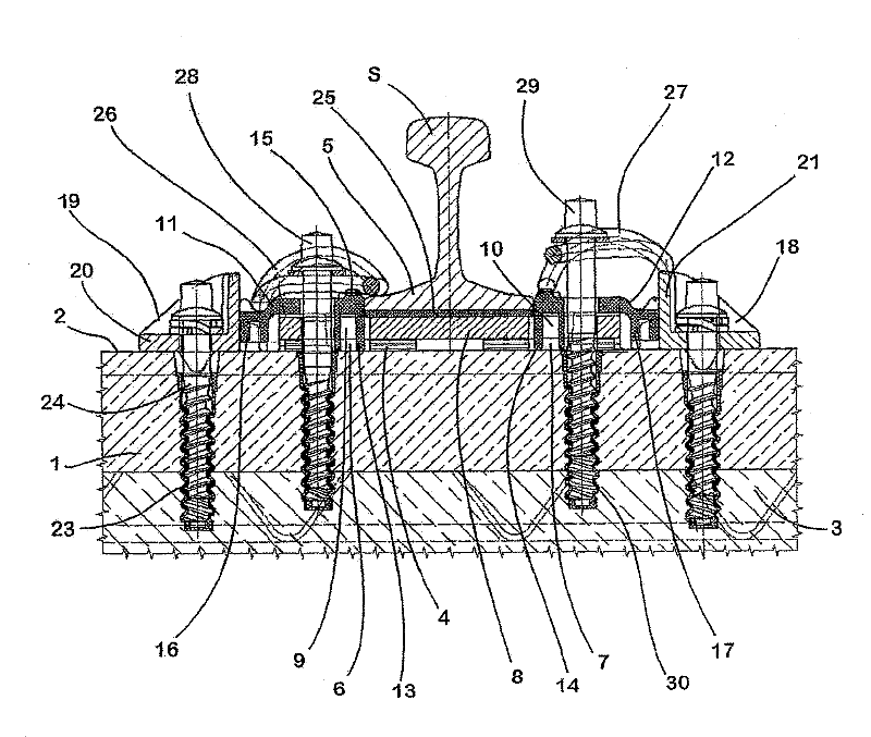
[0022] exist figure 1 In the rail installation shown, the rail S is a conventional straight rail mounted on a concrete sleeper 1 having a flat upper side 2 and resting on a base plate 3 also made of concrete. In order to fix the sleepers 1 on the base plate 3 , filling concrete (not shown) can be poured into the gap between two adjacent sleepers 1 . The mounting system for mounting the rail S to the sleeper 1 includes the components described below.

[0023] An elastic intermediate layer 4 is applied to the flat upper side 2 of the concrete sleeper 1 and, viewed from the transverse direction, to the longitudinally extending steel rail S, on the basis of which the elastic intermediate layer 4 is positioned centrally. The width B of the elastic intermediate layer 4 is greater than the width of the rail base 5 of the rail S, so that the intermediate layer 4 protrudes beyond the rail base 5 on both sides. The intermediate layer 4 has corresponding openings 6 , 7 in the region pr...


PUM


Abstract

In the case of a rail-fixing system according to the invention, the individual elements are arranged on the flat surface (2) of the firm underlying surface (1) available in each case. In this case, the positional fixing of an angular guide plate (11, 12) does not take place via projections or depressions formed on the underlying surface (1) but rather via a separate angle bracket (18, 19). Duringthe installation of the fixing system according to the invention, this angle bracket (18, 19) can easily be positioned in each case in such a manner that optimum support of the angular guide plate (11, 12) is ensured irrespective of its particular orientation on the particular underlying surface. The fixing system according to the invention can thereby build on a known system from which it takes most of the components, such as the elastic intermediate layer (4), pressure-distributing plate (8), spring element (26, 27) and clamping element (28, 29).

Description

technical field [0001] The invention relates to a rail installation system, in particular to an installation system for installing a rail in a turnout on a flat integral ballast bed. Background technique [0002] A foundation made of concrete or a similar solid, rigid material, the so-called "ballastless track", has the advantage that a rolling stock traveling at high speeds causes transverse tension, with the aid of which a high The inherent rigidity of the steel can reliably absorb the considerable tension caused by the lateral tension of the rolling stock, thereby avoiding the risk of unacceptable deformation of the rails and foundations. However, in terms of strain, in order to ensure the deformation capacity of the rail installation (this deformation capacity is necessary during the use of the rail), the rail is usually supported on the foundation by using an elastic middle layer. The spring element acts on the rail base from above downwards, pressing the rail with a d...

Claims


Application Information

Patent Timeline
Patent Type & Authority Patents(China)
IPC IPC(8): E01B9/68E01B9/38
CPCE01B9/68E01B9/38
Inventor 赫尔穆特·艾森贝格温弗里德·博斯特林迪尔克·福德布鲁克
Owner VOSSLOH WERKE GMBH
Why Eureka
Try Eureka