Vibration actuator
A technology of vibrating actuators and vibrating components, applied in piezoelectric/electrostrictive/magnetostrictive devices, generators/motors, piezoelectric effect/electrostrictive or magnetostrictive motors, etc., can solve the problem of device complication etc.
- Summary
- Abstract
- Description
- Claims
- Application Information
AI Technical Summary
Problems solved by technology
Method used
Image

Examples
no. 1 Embodiment approach
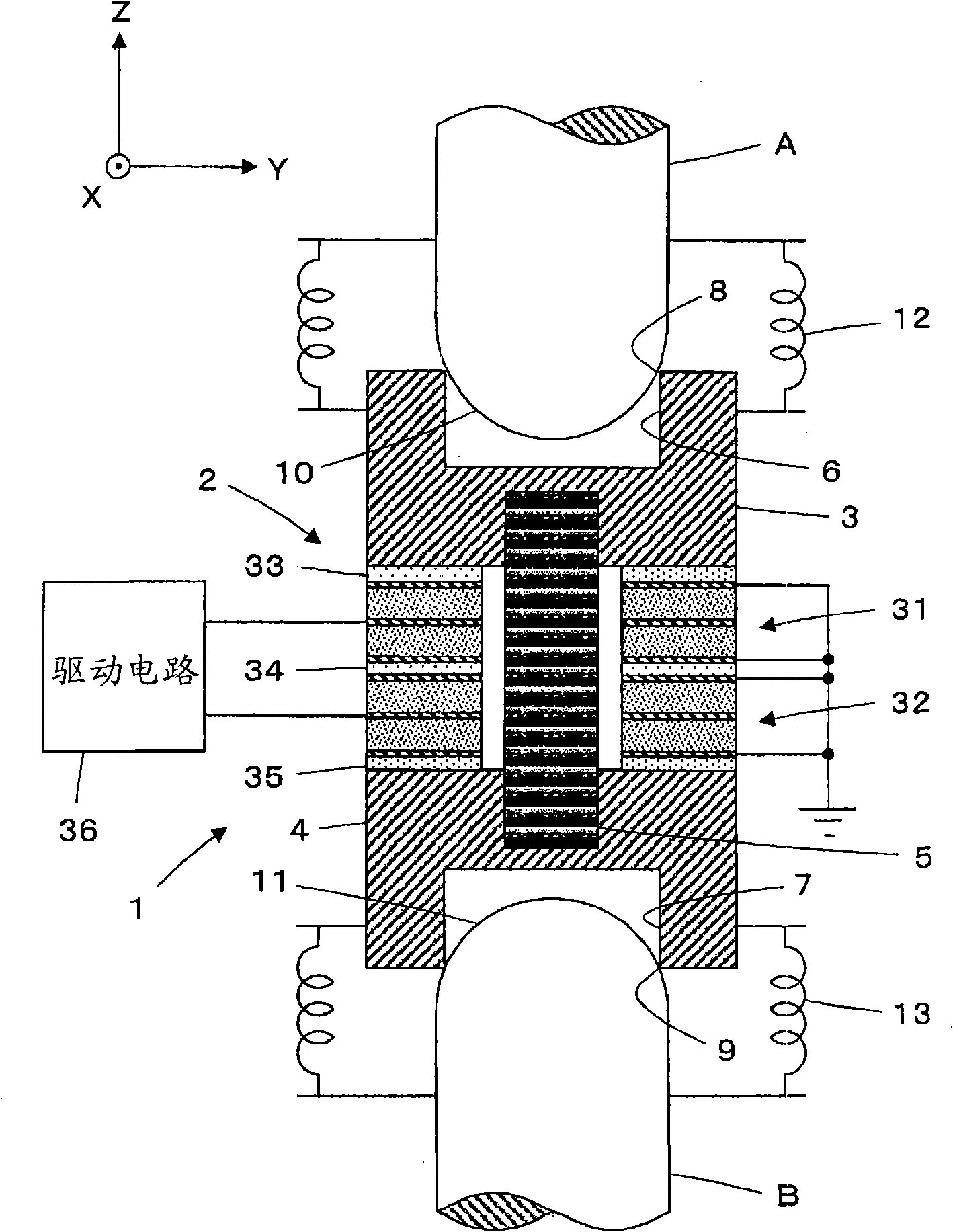
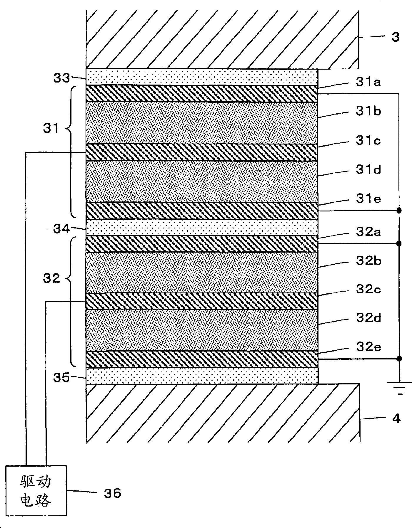
[0031] figure 1 shows the vibration actuator according to the first embodiment of the present invention. This vibration actuator is an ultrasonic actuator that uses ultrasonic vibration to rotate a rotor, and includes an actuator main body 1 and two rotors A and B necessary for rotationally driving the actuator main body 1 . The actuator main body 1 has a cylindrical composite vibrator 2 and a first stator 3 and a second stator 4 respectively arranged at both ends of the composite vibrator 2 . The first stator 3 and the second stator 4 sandwich the composite vibrator 2 and are connected to each other by connecting bolts 5 passing through the composite vibrator 2 to form an actuator body 1 with an approximately cylindrical shape. Here, for the convenience of description, the central axis of the actuator body 1 from the second stator 4 toward the first stator 3 is defined as the Z axis, the X axis extends in the vertical direction of the Z axis, and the Y axis is related to the...
no. 2 Embodiment approach
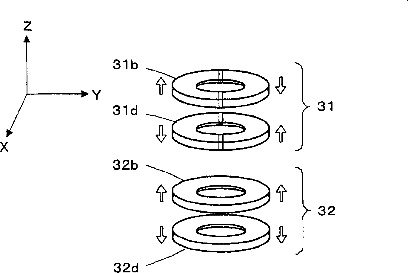
[0054] Next, refer to Figure 12 A vibration actuator according to a second embodiment of the present invention will be described. In this second embodiment, in addition to the first embodiment, the composite vibrator 2 has the first piezoelectric element portion 31 that generates flexural vibration in the Y-axis direction and the second piezoelectric element portion 31 that generates longitudinal vibration in the Z-axis direction. In addition to the element portion 32, a third piezoelectric element portion 41 that generates flexural vibration in the X-axis direction is provided. The third piezoelectric element portion 41 has Figure 13 A pair of piezoelectric element plates 41b and 41d are shown. The two portions divided in the X-axis direction of the pair of piezoelectric element plates 41b and 41d have opposite polarities, and are polarized to exhibit opposite deformation behaviors of expansion and contraction in the Z-axis direction (thickness direction), respectively. ...
no. 3 Embodiment approach
[0059] Next, refer to Figure 14 A vibration actuator according to a third embodiment of the present invention will be described. The third embodiment is to replace the springs 12 and 13 used in the first embodiment and use a freely expandable rubber sleeve 51, so that the two rotors A and B are pressurized and respectively connected to the corresponding stators 3 and 4 touch. The rubber sleeve 51 has a cylindrical shape and covers the entire outer peripheral portion of the actuator body 1, and at the same time, its two ends are respectively fixed to the ends of the first rotor A and the second rotor B in a state stretched along the direction of the central axis. Peripheral parts. Utilizing the force of the rubber sleeve 51, the two rotors A and B are pressurized and come into contact with the corresponding corners 8 and 9 of the stators 3 and 4, respectively. Therefore, as in the first embodiment, the two rotors A and B can be driven to rotate by one composite vibrator 2 ....
PUM
 Abstract
Description
Claims
Application Information
 - R&D
- Intellectual Property
- Life Sciences
- Materials
- Tech Scout
- Unparalleled Data Quality
- Higher Quality Content
- 60% Fewer Hallucinations
Browse by: Latest US Patents, China's latest patents, Technical Efficacy Thesaurus, Application Domain, Technology Topic, Popular Technical Reports.
© 2025 PatSnap. All rights reserved.Legal|Privacy policy|Modern Slavery Act Transparency Statement|Sitemap|About US| Contact US: help@patsnap.com