Four-short shock exciting motor elliptical vibrating screen coupled with torsion springs

A technology of exciting motor and torsion spring, applied in the direction of filter screen, mobile filter element filter, grille, etc., can solve the problem that the effective exciting force of the vibrating screen is reduced, the electromechanical coupling cannot be avoided, and the effective exciting force cannot be increased. and other problems, to achieve the effect of close power consumption, low noise, and small footprint

Active Publication Date: 2017-02-22
SOUTHWEST PETROLEUM UNIV
View PDF7 Cites 7 Cited by
  • Summary
  • Abstract
  • Description
  • Claims
  • Application Information

AI Technical Summary

Problems solved by technology

When dual excitation motors are used, the total excitation force is limited, and it is difficult to meet the requirements of the excitation force required for large-area and high-efficiency screening of vibrating screens
ZL200910187748.6 adopts four excitation motors for self-synchronous vibration. The four excitation motors are divided into two pairs and installed symmetrically on the vibration motor bases of the two auxiliary rigid body units. There is no connection between each pair of vibration motors. , to realize the linear motion track of the vibrating screen, two auxiliary rigid bodies are symmetrically installed on the position of the screen body with the longitudinal axis as the symmetrical axis. The vibrating motors will appear in an anti-phase synchronous state. This structure cannot avoid the electromechanical coupling between each pair of motors running in the same direction. The phase difference an...

Method used


Image

  • Four-short shock exciting motor elliptical vibrating screen coupled with torsion springs
  • Four-short shock exciting motor elliptical vibrating screen coupled with torsion springs
  • Four-short shock exciting motor elliptical vibrating screen coupled with torsion springs

Examples


Embodiment Construction

[0016] Embodiments of the present invention will be specifically described below in conjunction with the accompanying drawings.

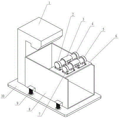
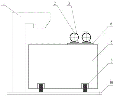
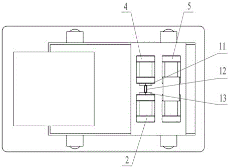
[0017] Such as figure 1 , figure 2 , image 3 , Figure 4 As shown, the elliptical vibrating screen with four short excitation motors coupled by torsion springs of the present invention consists of a feed hopper 1, a first excitation motor 2, a shield 3, a second excitation motor 4, a third excitation motor 5, and a motor base 6. The fourth excitation motor 7, the screen box 8, the vibration isolation spring 9, the base 10, the second coupling eccentric mass 11, the first torsion spring 12, the first coupling eccentric mass 13, the fourth coupling eccentric mass 14, the second The torsion spring 15 and the third coupling eccentric block 16 are composed.

[0018] The plane on which the motor is installed on the motor base 6 is parallel to the screen surface, or at a smaller angle, the first vibration motor 2 and the second vibration motor 4 are ...


PUM


Abstract

The invention discloses a four-short shock exciting motor elliptical vibrating screen coupled with a torsion spring. The four-short shock exciting motor elliptical vibrating screen coupled with the torsion spring mainly consists of a feed hopper, four shock exciting motors, a protective cover, a motor base, a screen box, a vibration isolation spring, a base, coupling eccentric blocks and the torsion springs. The shock exciting motors are pairwise coaxially mounted on the motor base in parallel; and the torsion springs connect the coupling eccentric blocks of two shock exciting motors with overlapped axes to absorb shock caused by starting of the two and to realize zero-phase synchronization of the two. Two coupled shock exciting motors adopt the same mass torques, and are synchronously started in the same direction. Two shock exciting motors near a feed end use higher eccentric mass torques; two shock exciting motors near a discharge end use lower eccentric mass torques; the two sets of shock exciting motors reversely rotate at the same speed; and the generated shock exciting force realizes an elliptic motion of the vibration screen. After stable operation, one of two coupled shock exciting motors is electrified. The vibrating screen can fully exert the shock exciting force of the shock exciting motors, realizes high vibrating amplitude, and is low in energy consumption and noise.

Description

technical field [0001] The patent of the invention relates to a vibrating screen for solid-liquid separation and solid material screening, especially a four-machine-driven translational elliptical vibrating screen with large screening area used in ore dressing, coal preparation, metallurgy, oil drilling and other operations. Background technique [0002] The translational elliptical vibrating screen can be realized by double excitation motors. When dual excitation motors are used, the total excitation force is limited, and it is difficult to achieve the excitation force required for large-area and high-efficiency screening of the vibrating screen. ZL200910187748.6 adopts four excitation motors for self-synchronous vibration. The four excitation motors are divided into two pairs and installed symmetrically on the vibration motor bases of the two auxiliary rigid body units. There is no connection between each pair of vibration motors. , to realize the linear motion track of t...

Claims


Application Information

Patent Timeline
IPC IPC(8): B07B1/28B07B1/42B01D33/03
CPCB01D33/03B01D33/0307B07B1/28B07B1/42
Inventor 侯勇俊方潘李芬杜明俊王钰文
Owner SOUTHWEST PETROLEUM UNIV
Why Eureka
Try Eureka