
Micro Scale Mechanical Rate Sensors

a mechanical rate sensor and micro-scale technology, applied in the direction of acceleration measurement using interia forces, speed measurement using gyroscopic effects, devices using electric/magnetic means, etc., can solve the problem of limited resolution of ring gyro, difficult micromachining of shell gyro, and inability to perfectly match the frequency of the ring gyro, etc. problem

Inactive Publication Date: 2011-03-03
RAMOT AT TEL AVIV UNIV LTD
View PDF24 Cites 7 Cited by
  • Summary
  • Abstract
  • Description
  • Claims
  • Application Information

AI Technical Summary

Benefits of technology

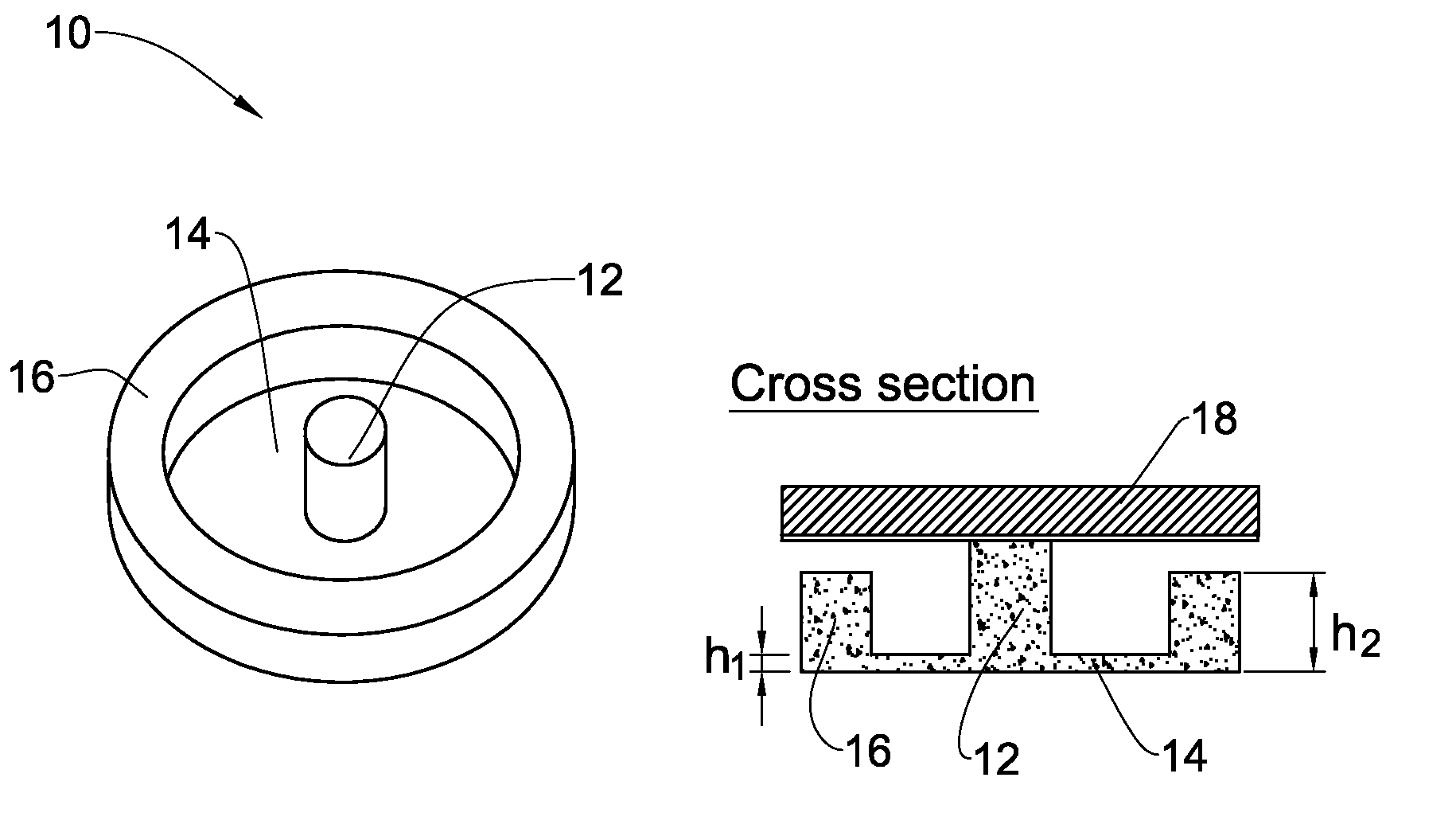
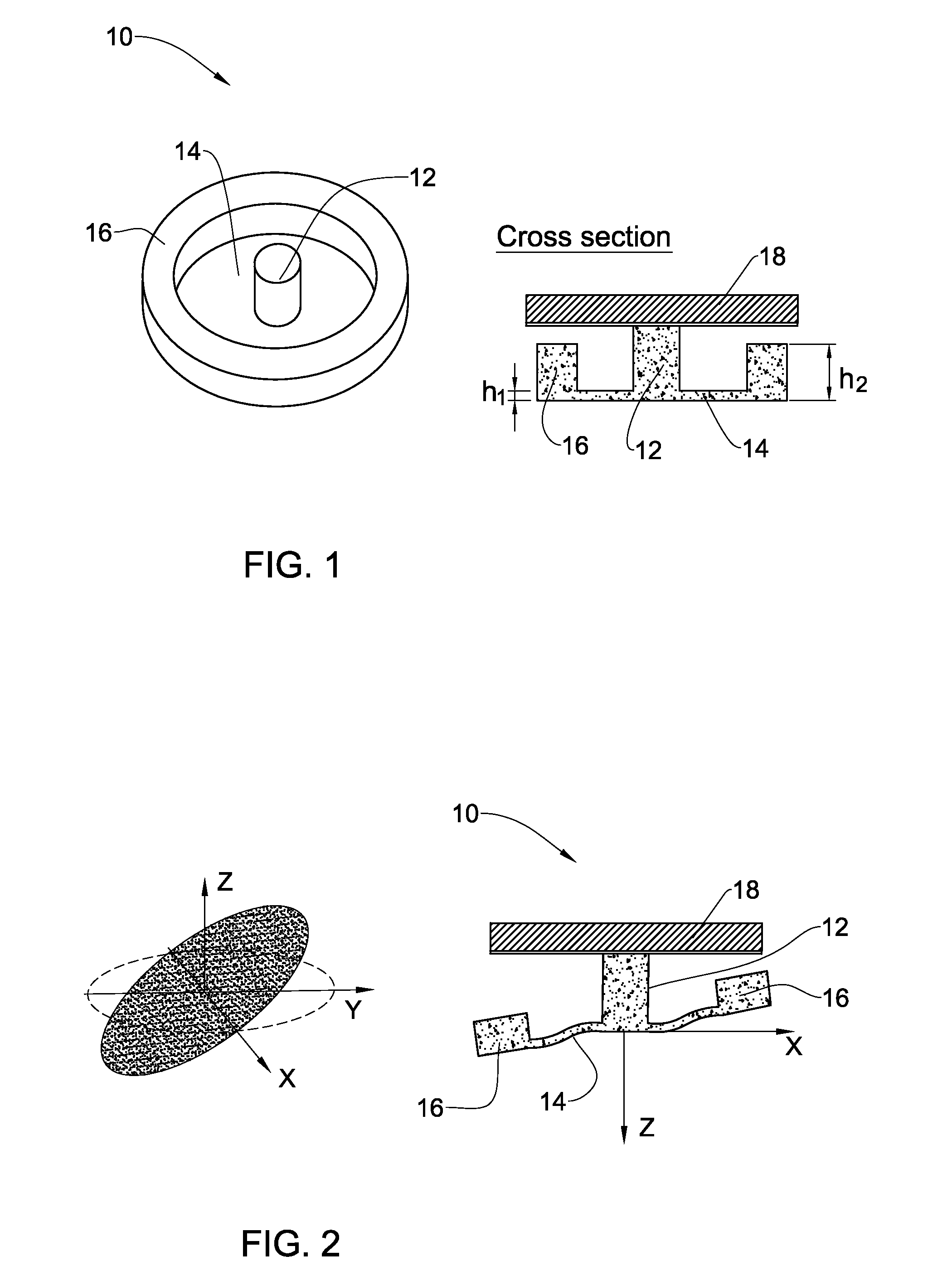
[0010]The device of the present invention has a disk-like plate. The disk-like plate is attached to a substrate (e.g. in its central point) in a manner to define a proof mass region within the disk, and is configured to perform a wave type precession motion. In some embodiments of the invention, the disk is coupled to the axis of rotation by its central part or peripheral ring part, and defines the proof mass region of the disk located at, respectively, the peripheral ring part or the central part of the disk. The configuration is such that an annular region of the disk, between its central and periphery parts, is deformable along a circumference thereof and also along axes perpendicular to the axis of the device rotation. This can be implemented by making this annular region appropriately flexible. Alternatively, the central post supporting the disk at its central point could have certain mechanical compliance allowing the precession wave type motion of the disk.
[0019]In the device of the present invention, the eigenfrequencies are matched automatically, and a small dimension of the shell is constituted by a thickness of an annular region (e.g. formed by an SOI device layer). The SOI wafers can be purchased with very high level of precision in the thickness of the device layer. As a result, the uncertainty in the flexible element stiffness is reduced dramatically. On the other hand, since the all thickness of the handle is used as a proof mass, the effective mass of the sensor is increased thereby improving significantly the sensitivity and reducing influence of the thermal noise. In the case of the small mismatch between the two tilting frequencies, the functionality of the device is preserved since the mismatch results in an elliptical precessions rather than a circular precession.
[0020]The motion of the proof mass is out of plane. This simplifies significantly the sensing and actuation. For example, in the case of electrostatic actuation and sensing, large area electrodes can be located under the proof mass, the gap between the electrodes and the proof mass is defined by the thickness of thin films and can be provided as small as necessary. In the case of magnetic actuation and sensing, large magnetic mass of the proof mass simplifies both actuation and sensing. The fact that the flexible annular plate is used as a spring element, provides for high resonant frequency and high mass velocity, which is beneficial for inertial measurement. Additional benefit from the plate type of the flexible element is the fact that the device is less prone to damages related to shock and environmental vibrations.
[0021]The device of the present invention is attached to the substrate by the central stand or by the periphery ring, and, as a result, does not exhibit wobble type motion, is intrinsically stable and does not require a closed loop control for stabilization.
[0030]According to another broad aspect of the invention, there is provided a method of manufacturing an angular rate sensor device, the method comprising patterning a disk-like structure to define a first region configured for coupling the structure to an axis of rotation, a second relatively thin annular region, and a third relatively thick, proof mass region, thereby enabling excitation for precession of the disk-shaped structure, while rotating along said axis parallel to the disk plane, to cause deformation of said relatively thin annular region along a circumference thereof and flexing of said relatively thin annular region along axes perpendicular to the axis of rotation, resulting in a detectable change of a precession phase indicative of the rate of the structure rotation.

Problems solved by technology

The main difficulty in this kind of devices is related to the fact that the frequencies cannot be perfectly matched due to low relative tolerances of microfabrication.
However, a shell gyro is difficult to fabricate using micromachining methods.
However, the performance, and mainly resolution of the ring gyro, is limited by a small mass of the ring and necessity to detect very small deflections.
In addition, the symmetry of the ring stiffness is typically not ideal due to suspension springs attached to it.
However, the control of the disk motion is usually very complex due to an intrinsic instability of a spinning disk while the fabrication is usually challenging or requires assembly steps.
In addition, in the case of magnetic levitation, levitation and control coils exhibit relatively high power consumption.

Method used


Image

  • Micro Scale Mechanical Rate Sensors
  • Micro Scale Mechanical Rate Sensors
  • Micro Scale Mechanical Rate Sensors

Examples


Embodiment Construction

[0039]Referring to FIG. 1, there is illustrated an example of an angular rate sensor, generally designated 10, according to the invention. The sensor device 10 is designed like a disk and has a flexible portion 14 which is coupled to a substrate 18 in a manner enabling a wave type precession motion of this portion 14, such that during this motion each material point of the portion 14 performs elliptic motion. More specifically, the device 10 has a central region (stand) 12, annular region (plate) 14 of a first small thickness h1 surrounding the central region 12, and a periphery ring-like region 16 of a second much larger thickness h2 surrounding the annular plate 14. The annular plate 14 thus presents a relatively flexible element or portion of device 10, while the outer ring-like member 16 presents a rigid element or portion. In this example, the above coupling between the flexible portion 14 and the substrate is achieved by attaching the central stand12 to the substrate 18 and co...


PUM

PropertyMeasurementUnit
Thicknessaaaaaaaaaa
Massaaaaaaaaaa
Flexibilityaaaaaaaaaa

Abstract

An angular rate sensor device is presented. The sensor device comprises a disk-shaped structure having a proof mass region and a flexible portion. The disk-like structure is coupled to a substrate in a manner enabling a wave type precession motion such that during the wave type precession motion each material point of the proof mass performs elliptic motion.

Description

RELATED APPLICATIONS[0001]This application is a Continuation of PCT application serial number PCT / IL2009 / 000243 filed on Mar. 3, 2009 which claims priority to U.S. Provisional application Ser. No. 61 / 033,182 filed on Mar. 3, 2008 both of which are incorporated herein by reference in their entirety.FIELD OF THE INVENTION[0002]This invention is in the field of mechanical rate sensors (gyroscopes) and relates to a micro scale angular rate sensor, particularly a sensor that can be fabricated by micromachining methods.BACKGROUND OF THE INVENTION[0003]Angular rate sensors are designed for measuring rotational velocity around the sensitive axis of the sensor. Such a device is typically composed of a rapidly spinning wheel or disk mounted on a shaft with various kinds of supports to allow it to spin freely. Its angular momentum resists the angular motion of its base about the two axes orthogonal to its spin axis. Angular rate sensors are used in conjunction with accelerometers to make a dyn...

Claims


Application Information

Patent Timeline
IPC IPC(8): G01C19/56B23P11/00
CPCY10T29/49826G01C19/56
Inventor KRYLOV, VIACHESLAVSCHREIBER, DAVIDSHACHAM-DIAMAND, YOSI
Owner RAMOT AT TEL AVIV UNIV LTD
Learn More