Swinging inner-connected meshed planetary gear structure

A planetary gear, internal gear technology, applied in the direction of gear transmission, belt/chain/gear, transmission, etc., can solve problems such as promoting wear and damage, and achieve the effect of preventing wear and preventing interference

Inactive Publication Date: 2009-02-11
SUMITOMO HEAVY IND LTD
View PDF1 Cites 5 Cited by
  • Summary
  • Abstract
  • Description
  • Claims
  • Application Information

AI Technical Summary

Problems solved by technology

[0009] In the case of a collision, if there is even a slight change in the tooth top of the sun gear 23, the tooth surface of the sun gear 23 or the external gears 28A, 28B will be damaged and wear will be accelerated.
In addition, it is also conceivable that the gear powder (iron powder) floating in the lubricating oil due to damage will have various adverse effects on other parts.

Method used


Image

  • Swinging inner-connected meshed planetary gear structure
  • Swinging inner-connected meshed planetary gear structure
  • Swinging inner-connected meshed planetary gear structure

Examples


Embodiment Construction

[0021] Hereinafter, an example of the embodiment of the present invention will be described in detail with reference to the drawings.

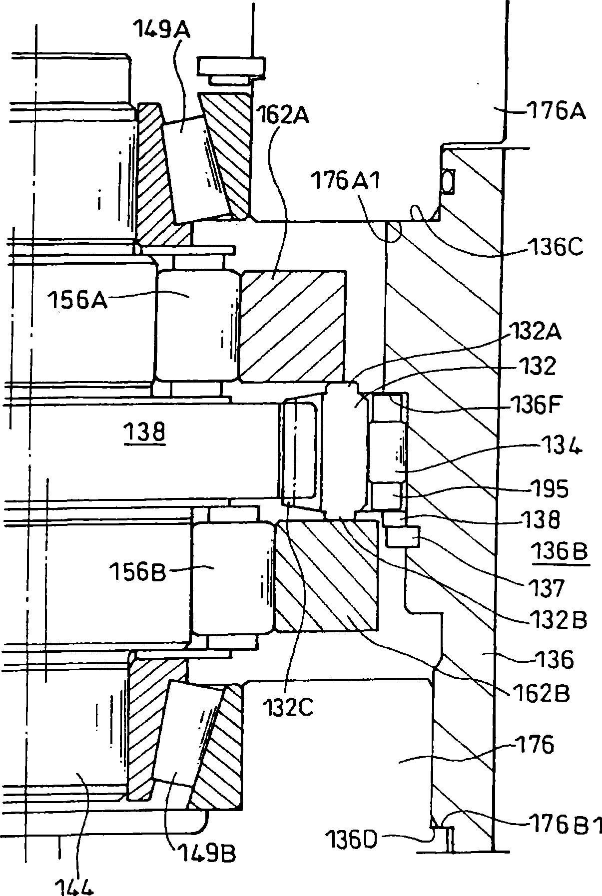
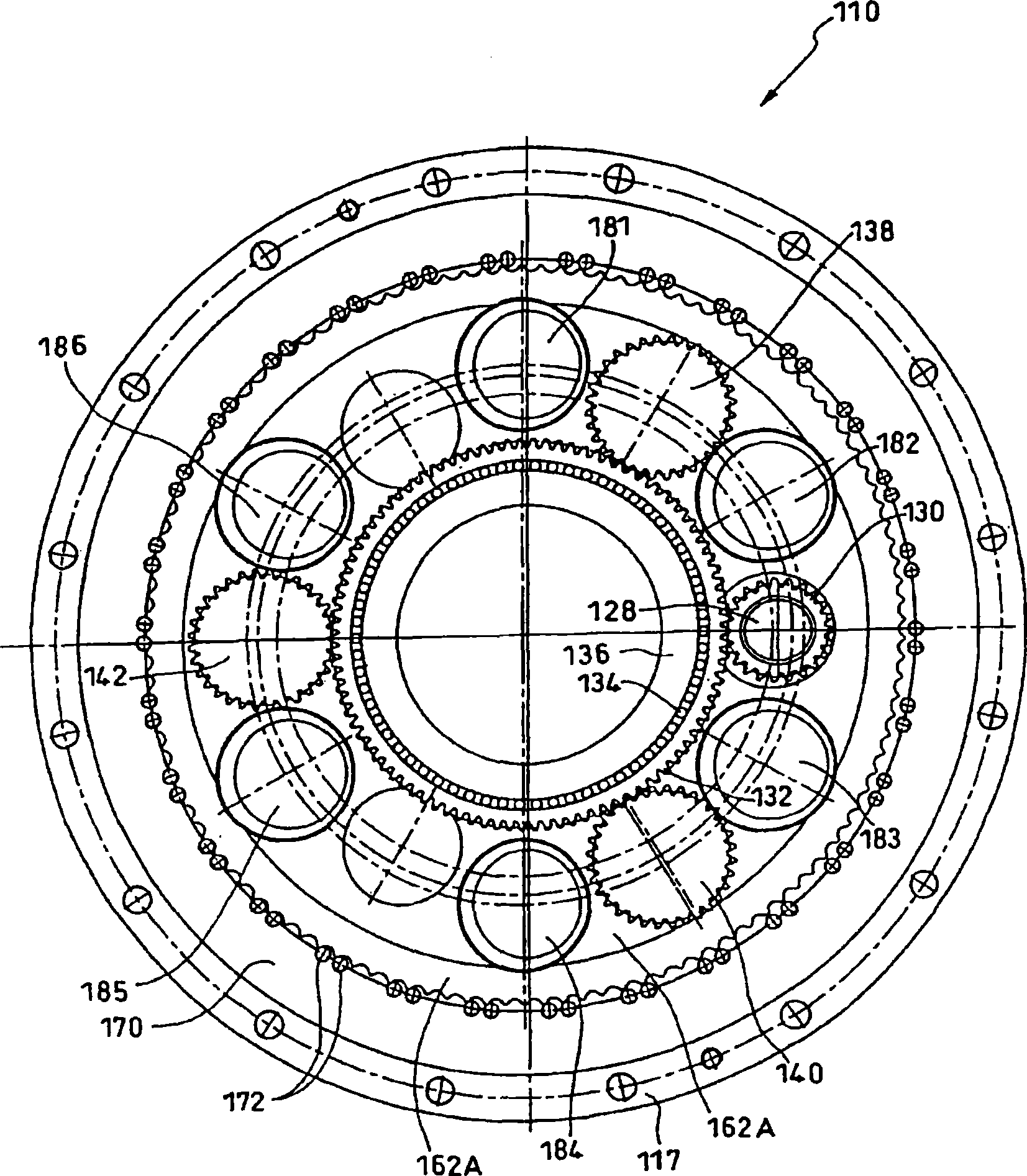
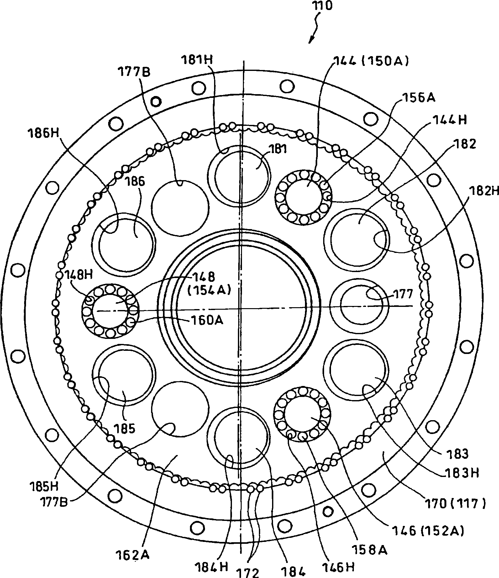
[0022] 4 is a cross-sectional view of a joint drive device of a robot using a swing internally connected planetary gear structure according to an example of an embodiment of the present invention; figure 1 It is an enlarged view of its main parts. In addition, figure 2 , image 3 They are cross-sectional views taken along the line II-II and line III-III of the arrows in FIG. 4, respectively.

[0023] The joint driving device 110 is assembled in a joint part of a robot (not shown), and the joint driving device 110 is rotatably supported and driven in a state where the joint driving device 110 is fixed to a base 112 constituting a part of the robot The movable part 114 of the other part of the robot.

[0024] As shown in FIG. 4, the joint driving device 110 is mainly composed of a motor 116 arranged on the movable member 114, and a reduction mecha...


PUM


Abstract

The invention provides a swing internal planetary gear structure. While in use, the unfavorable conditions caused by impact between an external gear and a central gear do not happen even the top end face of the central gear is not processed. The swing internal planetary gear structure comprises external gears (162A, 162B) which swing and rotate through eccentric bodies (150A, 150B, 152A, 152B, 154A, 154B); and an internal gear (170) engaged with the external gears. The invention is characterized in that the central gear (132), which is driven by a driving power and drives the several eccentric body shafts (144, 146, 148) synchronously, is axially connected with the external gears so that convex portions (interference prevention portions) (132A, 132B) of the toothed portion (132C) of the central gear is located between the central gear (132) and the external gears; it is characterized in that the convex portions are not contacted with the external gears.

Description

Technical field [0001] The invention relates to a swing internally connected planetary gear structure. Background technique [0002] For example, Patent Document 1 proposes a gear device with a planetary gear structure for driving the swing of a joint portion of a robot. Such as Figure 6 As shown, the gear device 10 rotatably supports and drives a movable member 14 constituting another part of the robot in a state of being fixed to a base 12 constituting a part of a robot (not shown). [0003] The gear device 10 is mainly composed of an electric motor 16 and a reduction mechanism portion 18. The power of the motor 16 is in the order of an input gear (not shown) mounted on the motor shaft 20, an external gear 22, an eccentric body shaft 24 shown in the figure, and an eccentric body shaft gear 25 provided on the eccentric body shaft 24 Pass and reach the sun gear 23. [0004] The sun gear 23 meshes with eccentric body shaft gears 25 (not shown) respectively provided on the other t...

Claims


Application Information

Patent Timeline
IPC IPC(8): F16H1/32
CPCF16H1/32
Inventor 芳贺卓左川雅弘为永淳
Owner SUMITOMO HEAVY IND LTD
Why Eureka
Try Eureka