Method for reducing data header expense

A data header and overhead technology, applied in the field of mobile communications, can solve the problems of reduced data transmission efficiency, increase of RLCPDU segmentation data header overhead, etc., and achieve the effect of reducing overhead

Active Publication Date: 2009-02-11
HUAWEI TECH CO LTD
View PDF0 Cites 21 Cited by
  • Summary
  • Abstract
  • Description
  • Claims
  • Application Information

AI Technical Summary

Problems solved by technology

[0015] It can be seen from the above-mentioned disclosed technical solutions that the main defect of the existing technology is: after the original

Method used


Image

  • Method for reducing data header expense
  • Method for reducing data header expense
  • Method for reducing data header expense

Examples


Example Embodiment

[0027] The technical solutions in the embodiments of the present invention will be clearly and completely described below in conjunction with the accompanying drawings in the embodiments of the present invention. Obviously, the described embodiments are only a part of the embodiments of the present invention, rather than all the embodiments. Based on the embodiments of the present invention, all other embodiments obtained by those of ordinary skill in the art without creative work shall fall within the protection scope of the present invention.

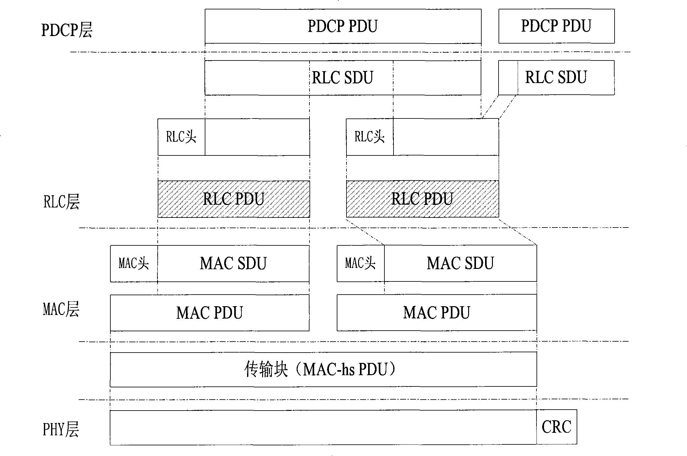
[0028] The embodiment of the present invention still uses Figure 5 The illustrated RLC PDU segmentation method is taken as an example for description.

[0029] In the embodiment of the present invention, the LSF field is expanded from 1 bit in the prior art to 2 bits, which is used to indicate the position of the RLC PDU segment obtained by re-segmentation in the original RLC PDU. When the LSF field indicates that the RLC PDU segment is ...


PUM


Abstract

The embodiment of the invention relates to the mobile communication field, in particular to a method for reducing the expenditure of a data head. The embodiment of the invention indicates the position of an RLC PDU segment in the original RLC PDU through the format of the data head of an expanded RLC PDU, and determines domains which can be omitted in the data head of the RLC PDU segment according to the position, thereby reducing the expenditure of the data head.

Description

technical field [0001] The invention relates to the field of mobile communication, in particular to a method for reducing data head overhead. Background technique [0002] The LTE (Long Term Evolution, long-term evolution) project is mainly aimed at the mobile communication architecture that the 3GPP organization plans to promote in the next 10 years, E-UTRAN (Evolved Universal Terrestrial Radio Access Network, evolved UMTS Terrestrial Radio Access Network), which is currently A set of system architecture that evolves from the 3G standard. [0003] figure 1 It is a schematic diagram of an E-UTRAN system in the prior art. Such as figure 1 As shown, the E-UTRAN system consists of a core network gateway, a base station and user equipment. [0004] figure 2 It is a schematic diagram of the user plane protocol architecture of the E-UTRAN system in the prior art. Such as figure 2 As shown, the layers from top to bottom are: PDCP (Packet Data Convergence Protocol, packet d...

Claims


Application Information

Patent Timeline
IPC IPC(8): H04L29/08H04L1/00H04L12/28
CPCH04W28/06H04L69/04H04W72/12
Inventor 邵飞
Owner HUAWEI TECH CO LTD
Why Eureka
Try Eureka