Particulate filter arrangement

一种颗粒过滤、颗粒过滤器的技术,应用在废气的颗粒过滤装置,废气颗粒过滤装置,颗粒过滤装置领域,能够解决颗粒过滤器满负载或堵塞、满负载、堵塞等问题,达到减少位置需求的效果

Inactive Publication Date: 2011-06-15
H 斯蒂格尔鲍尔
View PDF0 Cites 0 Cited by
  • Summary
  • Abstract
  • Description
  • Claims
  • Application Information

AI Technical Summary

Problems solved by technology

Particulate filters, while removing soot from the exhaust, have the following problem: If too many soot particles accumulate in the filter, it can clog or become fully loaded
Full loading or clogging of particulate filters is a significant problem in practice for normal diesel engines, for which the prior art does not have adequate remedies

Method used


Image

  • Particulate filter arrangement
  • Particulate filter arrangement
  • Particulate filter arrangement

Examples


Embodiment Construction

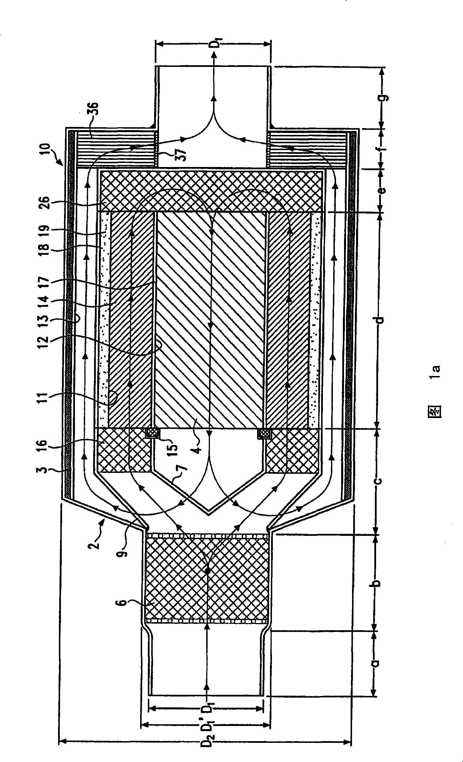
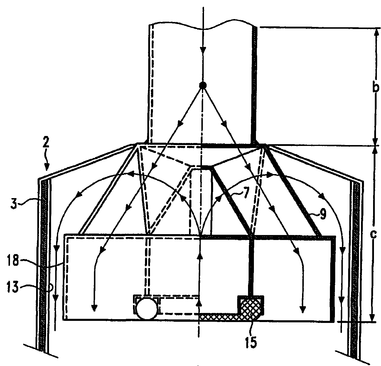
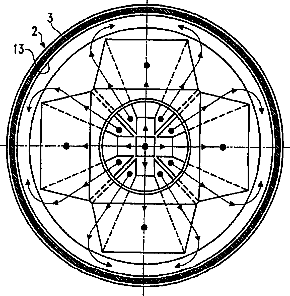
[0039] refer to Figures 1a to 1c A first exemplary embodiment of a particle filter device 10 according to the invention will be described in detail below with regard to its structure and function in the sectional view shown. Figure 1a A largely schematic longitudinal section through a particle filter device 10 according to the invention is shown. The particle filter device 10 according to the invention is located in the main flow direction of the exhaust gas (in the direction from the inlet to the outlet, that is to say in the Figure 1a and 2a from left to right) with an inlet section a, a filter forward section b, a forward diversion section or a first section c (in Figure 1a is very briefly indicated), a filter section or second section d, a rear steering section or third section e, a filter extension section f and an outlet section g, which All designed in a common housing 2 . The particle filter device 10 is connected via an inlet section a, for example, to a motor...


PUM


Abstract

Disclosed is a particulate filter assembly for filtering exhaust gases of an internal combustion engine, especially a diesel engine, comprising an inlet and an outlet. At least one particulate filter is disposed between the inlet and the outlet in the flow path of the exhaust gases. The exhaust gases are conducted inside a pipe that is provided with a first section in which the exhaust gases are conducted substantially towards the outlet. Said pipe is provided with a second section in which the exhaust gases are conducted essentially towards the inlet. In order to very quickly obtain a sufficiently high operating temperature of the assembly to prevent the filter from being fully loaded, the pipe is further provided with a third section in which the exhaust gases are conducted substantially towards the outlet.

Description

technical field [0001] The invention relates in principle to the field of aftertreatment of exhaust gases. More precisely, a first aspect of the invention relates to a particle filter device for filtering the exhaust gas of an internal combustion engine, in particular a diesel internal combustion engine, which has an inlet and an outlet, wherein in the flow path of the exhaust gas between the inlet and the outlet At least one particle filter is arranged in between, wherein the exhaust gas is flow-guided in a line, wherein the line has a first section, in which the exhaust gas flows substantially in the direction of the outlet, wherein the line also has a second A section in which the exhaust gas flows substantially in the direction of the inlet. According to a second aspect, the invention relates to a particle filter device for filtering the exhaust gas of an internal combustion engine, in particular a diesel internal combustion engine, which has an inlet and an outlet, where...

Claims


Application Information

Patent Timeline
Patent Type & Authority Patents(China)
IPC IPC(8): F01N3/021F01N3/025
CPCF01N2250/02F01N2013/026F01N2490/06F01N2330/60Y02T10/20F01N2240/20F01N2013/045F01N3/021F01N13/017F01N13/0097Y02T10/12F01N3/025
Inventor H·斯蒂格尔鲍尔
Owner H 斯蒂格尔鲍尔
Why Eureka
Try Eureka