
Axial fatigue experimental approach and apparatus for stacking abrasion load

A technology of fatigue experiment and fatigue testing machine, which is applied in the field of axial fatigue experiment method and device of superimposed wear load, which can solve problems such as inconsistent service life, large difference in service life, changes in fatigue life and fatigue strength, and achieve fatigue life Improvement, overcoming one-sidedness, light and small effect of the device

Inactive Publication Date: 2011-07-06
GUIZHOU UNIV
View PDF0 Cites 0 Cited by
  • Summary
  • Abstract
  • Description
  • Claims
  • Application Information

AI Technical Summary

Problems solved by technology

[0002] At present, fatigue tests mainly include bending fatigue and axial fatigue tests, and components are often subjected to various loads during actual use, such as corrosion, temperature, wear, extrusion and other loads and fatigue loads, resulting in fatigue life Significant changes in fatigue strength
The fatigue test in the laboratory is generally a single fatigue test, such as a separate axial fatigue test, or a separate friction load test, which has a certain one-sidedness, and it is difficult to apply multiple loads on the test piece at the same time. Fatigue test and friction load experiment, so the life predicted by the laboratory fatigue test is quite different from the actual service life of the component
The life predicted by the experiment does not match the actual service life

Method used


Image

  • Axial fatigue experimental approach and apparatus for stacking abrasion load
  • Axial fatigue experimental approach and apparatus for stacking abrasion load
  • Axial fatigue experimental approach and apparatus for stacking abrasion load

Examples


Embodiment Construction

[0014] The present invention will be described in further detail below in conjunction with the examples, but not as a limitation to the present invention.

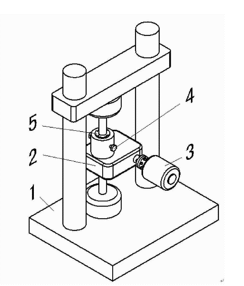
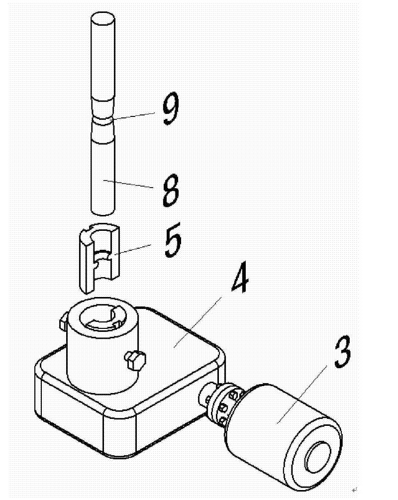
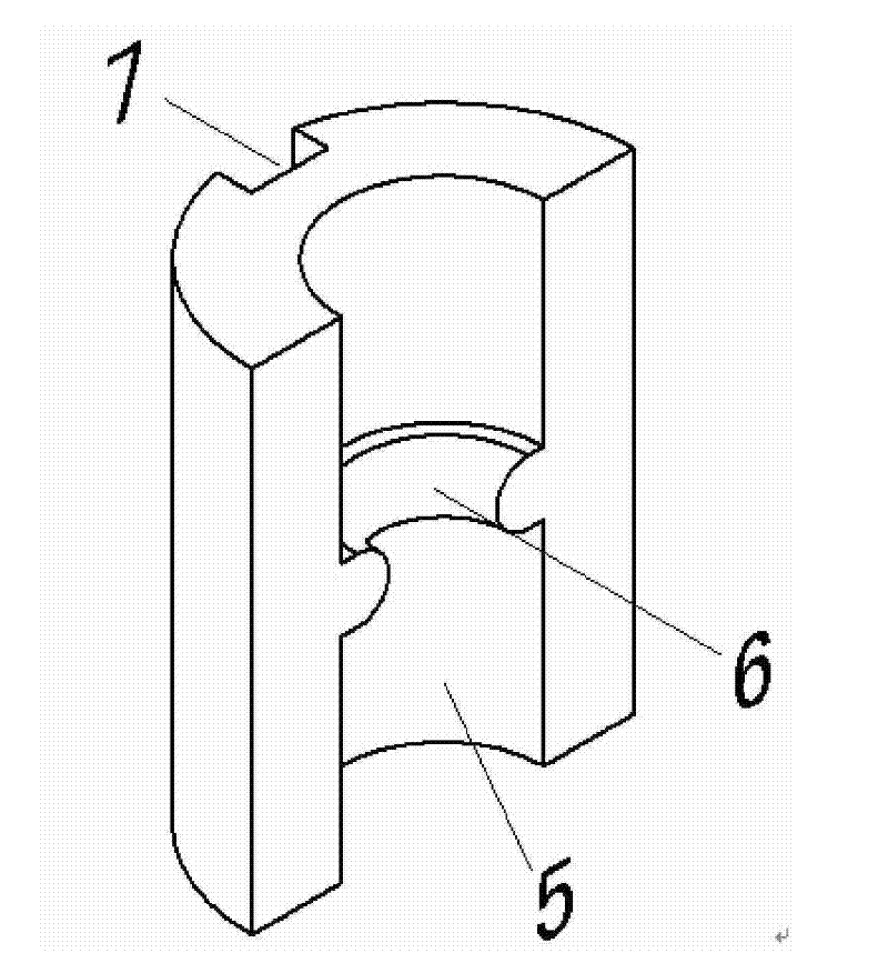
[0015] Embodiments of the invention. An axial fatigue test method with superimposed wear loads, such as figure 1 and figure 2 shown. The method is to apply a wear load on the test piece 8 while the axial fatigue testing machine 1 is performing an axial fatigue test on the test piece 8; The friction plate 5 on the wear load device applies a friction load to the test piece 8. The pressure of the friction load is realized by adjusting the pressure of the adjustment screw 4 on the back of the friction plate. The friction speed of the friction load is realized by adjusting the speed of the speed-regulating motor 3. The rotating speed is adjustable from 0 to 200r / min.

[0016] The axial fatigue test device of the superimposed wear load constructed according to the axial fatigue test method of the aforementioned superimposed...


PUM


Abstract

The present invention discloses an axial fatigue test method with abrasion load superposition and a device thereof. The method is to impose the abrasion load on the specimen when an axial fatigue test machine carries out the axial fatigue experiment on the specimen; and the abrasion load is imposed through an abrasion load device sleeved on the specimen. The device comprises the axial fatigue test machine and the abrasion load device; the abrasion load device comprises a speed reducer; the input shaft of the speed reducer is connected with an adjustable speed motor; the output shaft of the speed reducer is a cylindrical structure; adjusting screws are symmetrically arranged at both sides of the output shaft of the speed reducer; and a friction plate is arranged inside the output shaft of the speed reducer. The axial fatigue test method with abrasion load superposition and the device thereof provided by the present invention enables the experimental results in the laboratory to truly reflect the actual service life of the component under various load effects and overcomes the one-sidedness of the existing experimental results. The axial fatigue test method with abrasion load superposition and the device thereof provided by the present invention helps finding out the fatigue fracture reasons and fatigue life prediction under the combined effect of simultaneous abrasion load and fatigue load bearing.

Description

technical field [0001] The invention relates to an experiment method and device, in particular to an axial fatigue experiment method and device for superimposed wear load. Background technique [0002] At present, fatigue tests mainly include bending fatigue and axial fatigue tests, and components are often subjected to various loads during actual use, such as corrosion, temperature, wear, extrusion and other loads and fatigue loads, resulting in fatigue life and fatigue strength changed significantly. The fatigue test in the laboratory is generally a single fatigue test, such as a separate axial fatigue test, or a separate friction load test, which has a certain one-sidedness, and it is difficult to apply multiple loads on the test piece at the same time. Fatigue test and friction load experiment, so the life predicted by the laboratory fatigue test is quite different from the actual service life of the component. The predicted life of the experiment does not match the ac...

Claims


Application Information

Patent Timeline
Patent Type & Authority Patents(China)
IPC IPC(8): G01N3/00
Inventor 梁益龙汪航
Owner GUIZHOU UNIV
Learn More