Connector for electronic card

A technology for connectors and electronic cards, which is applied in the direction of connection, parts and circuits of connecting devices, etc., can solve problems such as difficulty in ensuring stable holding, failure of supporting iron sheets and guiding mechanism to be flatly attached, interference with the first electronic card, etc. , to achieve the effect of convenient assembly, simple structure, and prevention of warping and deformation

Inactive Publication Date: 2009-02-18
FOXCONN (KUNSHAN) COMPUTER CONNECTOR CO LTD +1
View PDF1 Cites 2 Cited by
  • Summary
  • Abstract
  • Description
  • Claims
  • Application Information

AI Technical Summary

Problems solved by technology

[0004] However, since the aforementioned triangular plate body is directly placed on the supporting iron sheet and there is no buckling device between the supporting iron sheet, a triangular plastic plate due to the guiding mechanism will be produced. The warping deformation of the body, the flatness of the lower iron sheet, or the influence of assembly tolerances cause a large gap between the supporting iron sheet and the guiding mechanism.
Therefore, when the first electronic card is inserted into the receiving space of the first connector, due to the large gap between the guide mechanism and the support iron piece, the support iron piece and the guide mechanism cannot be flattened, thereby interfering with the first electronic card. card insertion
Moreover, the first connector and the second connector are stacked only by passing the bolts through the screw holes at the rear end, resulting in a positional deviation between the triangular plate and the supporting iron sheet, and it is difficult to ensure the stable holding of the two

Method used


Image

  • Connector for electronic card
  • Connector for electronic card
  • Connector for electronic card

Examples


Embodiment Construction

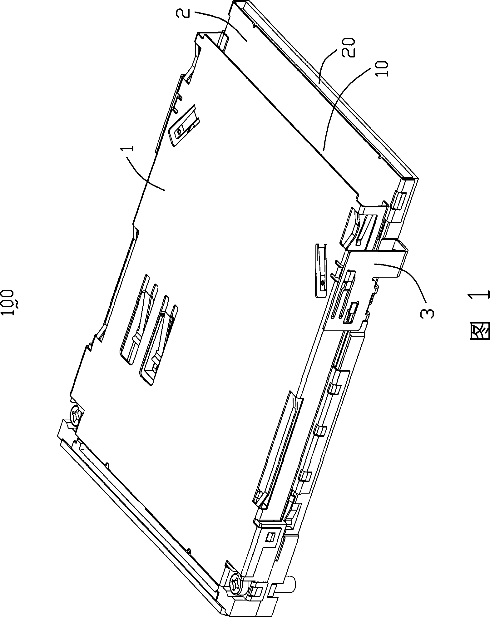
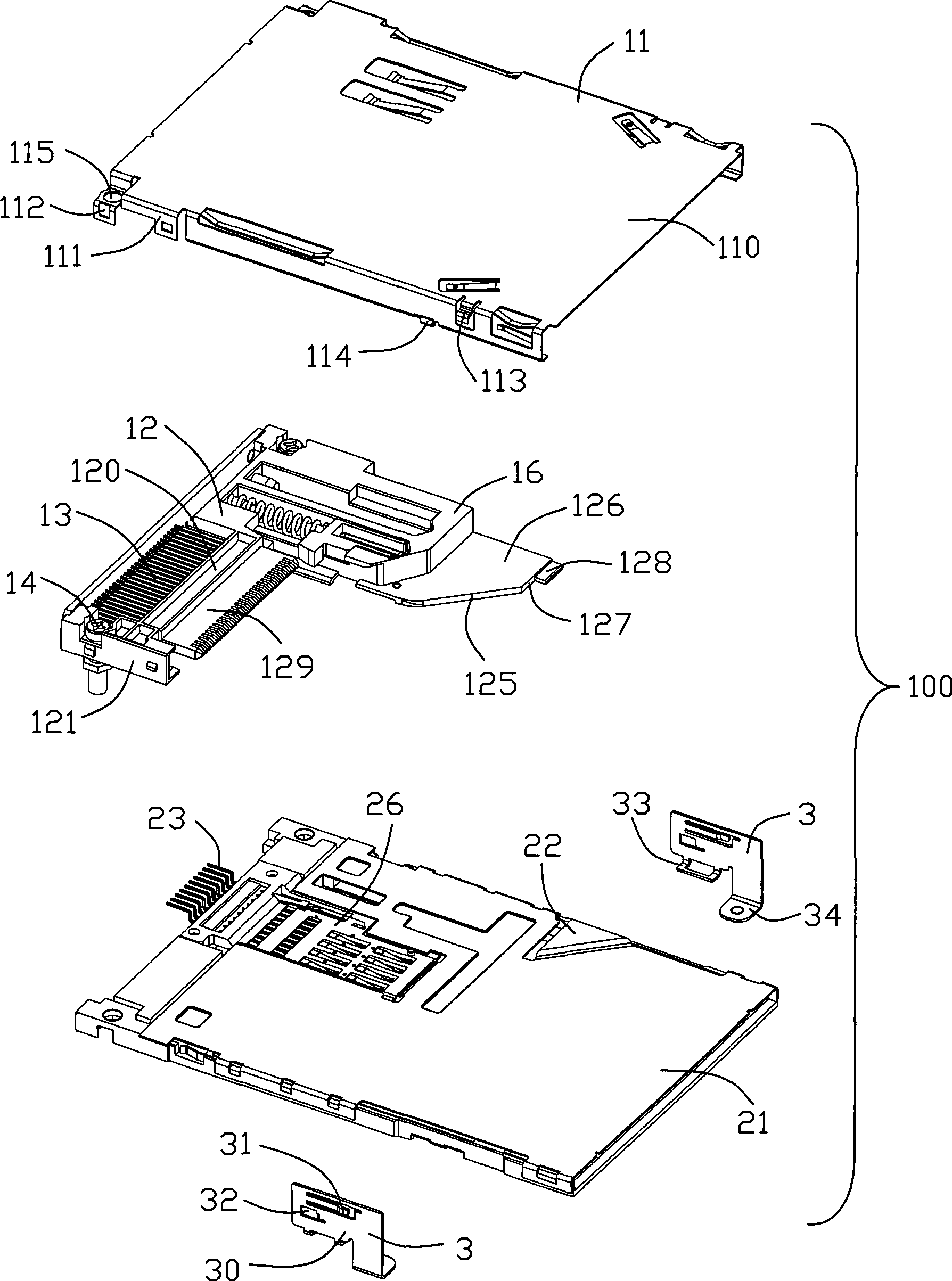
[0015] In the following, we will combine Figure 1 to Figure 5 The specific implementation manner of the electronic card connector 100 of the present invention will be introduced in detail. The electronic card connector 100 of the present invention is provided with a first connector 1 and a second connector 2 respectively for accommodating two different electronic cards. The first connector 1 includes an insulating body 12 and covers the insulating body 12. The first shielding shell 11 and the first conductive terminal 13 passing through the insulating body 12 , the insulating body 12 and the first shielding shell 11 define the first receiving space 10 . The second connector 2 is arranged below the first connector 1, and the two are arranged in a stacked manner. The second connector 2 includes a terminal module 26, a second conductive terminal 23 fixed in the terminal module 26, and terminals The module 26 cooperates with the fixed second shielding shell 21 and a bottom plate...


PUM


Abstract

An electric card connector includes a first connector and a second connector. The first connector includes an insulated main body, a plurality of conductive terminals accepted in the insulated main body and a first shielding shell body shielded on the insulated main body. The second connector installed with the first connector in stacked includes a second shielding shell body, a bottom plate installed under the second shielding shell body and a plurality of conductive terminals. The insulated main body cooperates with the second shielding shell so as to form a guide component capable of guiding to electronic card to insert. The structure is capable of steadily stacking the first and second connectors, and preventing shape distortion of the guide plate plastic or positional deviation of the first and second connectors. And this structure is simply structured and conveniently assembled.

Description

【Technical field】 [0001] The invention relates to an electronic card connector, in particular to an electronic card connector with stable structure. 【Background technique】 [0002] Since its inception, flash memory has been favored by consumers because of its attractive features such as powerful computing functions, fast speed, high expandability, and high storage density. Due to the many functions and characteristics of flash memory, some related companies use flash memory to develop various types of electronic cards, such as SD cards, MS cards, CF cards, XD cards and other specifications of electronic cards. Now many digital consumer products, such as mobile phones, digital cameras, digital cameras and PDAs, have become more and more dependent on such electronic cards. Moreover, due to the current semiconductor technology is becoming more and more sophisticated, the storage density and transmission speed of flash memory have grown by leaps and bounds, so that electronic c...

Claims


Application Information

Patent Timeline
IPC IPC(8): H01R12/16H01R13/629H01R13/631H01R12/71
Inventor 张蔚正
Owner FOXCONN (KUNSHAN) COMPUTER CONNECTOR CO LTD
Why Eureka
Try Eureka