Pulse arc welding control method

A control method and pulsed arc technology, which is applied in arc welding equipment, welding equipment, manufacturing tools, etc., can solve the problems such as the limit of molten pool shaking and poor arc stability, so as to improve the effect of bubble reduction, suppress arc instability, The effect of suppressing undershoot and overshoot

Active Publication Date: 2009-03-04
DAIHEN CORP
View PDF1 Cites 38 Cited by
  • Summary
  • Abstract
  • Description
  • Claims
  • Application Information

AI Technical Summary

Problems solved by technology

However, in the prior art, the stability of the arc is poor when the voltage setting value and pulse parameters are changed more than this, so there is a limit to the shaking effect of the molten pool.

Method used


Image

  • Pulse arc welding control method
  • Pulse arc welding control method
  • Pulse arc welding control method

Examples


Embodiment approach 1

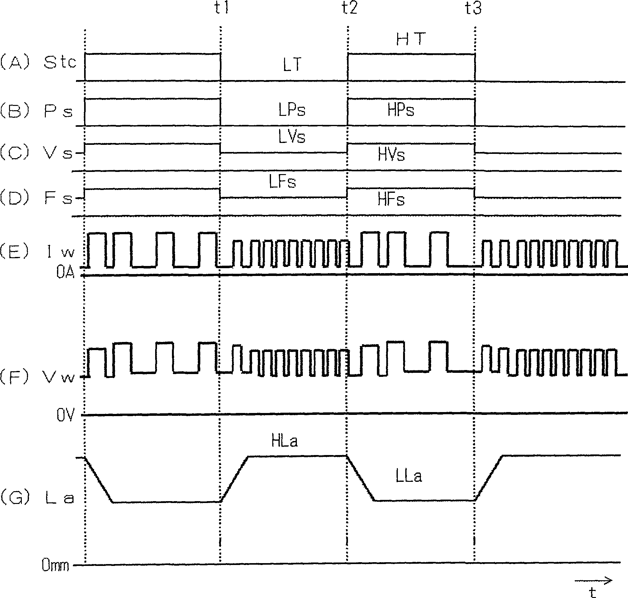
[0113] figure 1 It is a timing chart showing the pulse arc welding control method according to Embodiment 1 of the present invention. The figure (A) shows the switching signal Stc, the figure (B) shows the pulse parameter setting signal Ps, the figure (C) shows the voltage setting signal Vs, and the figure (D) shows the speed setting signal Fs, the The graph (E) shows the welding current Iw, the graph (F) shows the welding voltage Vw, and the graph (G) shows the arc length La. Hereinafter, description will be made with reference to this figure.

[0114] As shown in (A) of the figure, the switching signal Stc is at low level during the low pulse period LT at predetermined times t1 to t2, and at high level during the high pulse period HT at predetermined times t2 to t3.

[0115] The pulse parameter setting signal Ps, as shown in (B) of the figure, is the low pulse parameter setting value LPs during the low pulse period LT, and is the high pulse parameter setting value HPs dur...

Embodiment approach 2

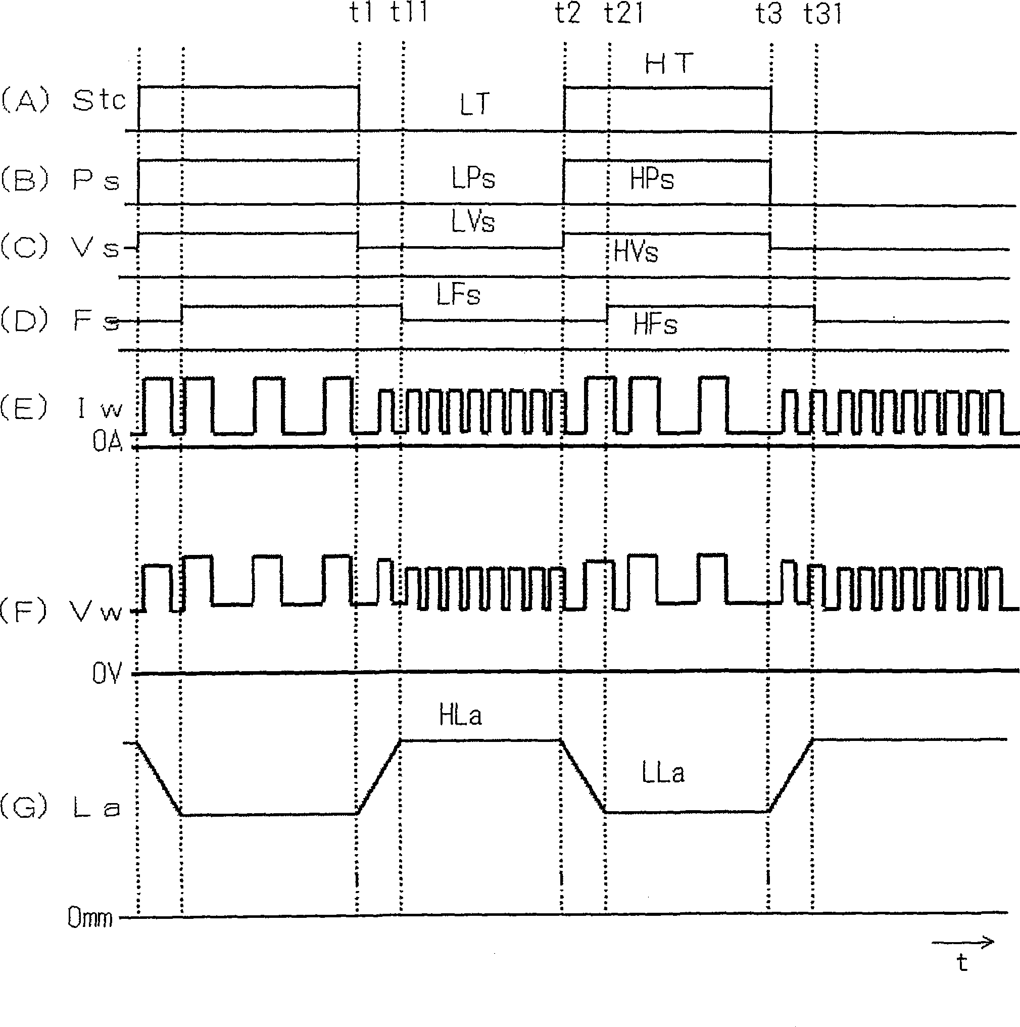
[0132] image 3 It is a timing chart showing the pulse arc welding control method according to Embodiment 2 of the present invention. This figure is similar to the above figure 1 Correspondingly, the signals shown in (A) to (G) of the figure are the same. The following pairs with figure 1 The different parts are explained with reference to this figure.

[0133] At time t1, as shown in (A) of the figure, when the switching signal Stc is at a low level (low pulse period), similarly to Embodiment 1, as shown in (B) of the figure, the pulse parameter setting signal Ps is The low pulse parameter setting value LPs, as shown in the figure (C), the voltage setting signal Vs is the low voltage setting value LVs. As a result, as shown in (G) of the figure, the arc length La changes from the low arc length LLa to the high arc length HLa, and converges from the transient state to the steady state at time t11. At time t11 when the transition state of the arc length La substantially ...

Embodiment approach 3

[0140] Figure 5 It is a time chart of the pulse arc welding control method in Embodiment 3 of this invention. This figure is similar to the above figure 1 Correspondingly, the signals shown in (A) to (G) of the figures are the same. Below, yes and figure 1 The different parts are explained with reference to this figure.

[0141] At time t1, as shown in (A) of the figure, when the switching signal Stc is at a low level (low pulse period), as in Embodiment 1, as shown in (D) of the figure, the sending speed setting signal Fs is Low feed speed setting value LFs. As a result, the feed speed changes from a speed corresponding to the high feed speed setting value HFs to a speed corresponding to the low feed speed setting value LFs, and the feed speed converges from a transient state to a steady state at time t12. At time t12 when the transitional state of the feeding speed is substantially convergent, as shown in (B) of the figure, the pulse parameter setting signal Ps becom...


PUM


Abstract

An impulse arc welding control method comprises: repeating electrifying using the electrifying of peak current of in peak period and the electrifying of background current in background period as impulse period; controlling the arc length in the manner that the welding voltage value (Vw) is approximately equal to the set voltage value (Vs); making the arc length to vary periodically by making the set voltage value (Vs) to vary synchronistically with the switching signal (Stc); making the impulse parameter (Ps) to vary synchronistically with the switching signal (Stc); and changing the sending speed (Fs) from the time the switching signal (Stc) varying starts to the time arc length (La) transition varying approximately converges. Thus, the major varying of arc force make the shake movement of the bath becomes more intensive to improve the air bubble reducing effect. Consequently, the air bubble reducing effect is improved in the impulse arc welding method with arc length varied periodically.

Description

technical field [0001] The present invention mainly relates to a pulsed arc welding control method for improving welding performance in a welding method in which generation of bubbles is controlled by shaking a molten pool by periodically changing an arc length. Background technique [0002] In pulsed arc welding, it is often used to periodically change the arc length by periodically changing the pulse parameters, welding voltage, etc., so that the melting range can be changed to obtain Figure 8 A welding method with a scaly and beautiful bead appearance as shown (hereinafter referred to as an arc length variation pulse arc welding control method). In addition, in this arc length change pulse arc welding, the weld pool can be shaken by changing the arc length, and the generation of air bubbles can be controlled. The arc length variation pulse arc welding method is mainly used for welding aluminum or aluminum alloy. This is because aluminum has good thermal conductivity and...

Claims


Application Information

Patent Timeline
Patent Type & Authority Applications(China)
IPC IPC(8): B23K9/09B23K9/10
Inventor 藤井督士上园敏郎
Owner DAIHEN CORP
Why Eureka
Try Eureka