Ink jet print head
An inkjet printing head and nozzle technology, applied in printing and other directions, can solve the problems of image quality reduction and unbalanced ejection performance, etc., and achieve the effect of improving balance
- Summary
- Abstract
- Description
- Claims
- Application Information
AI Technical Summary
Problems solved by technology
Method used
Image
Examples
no. 1 approach
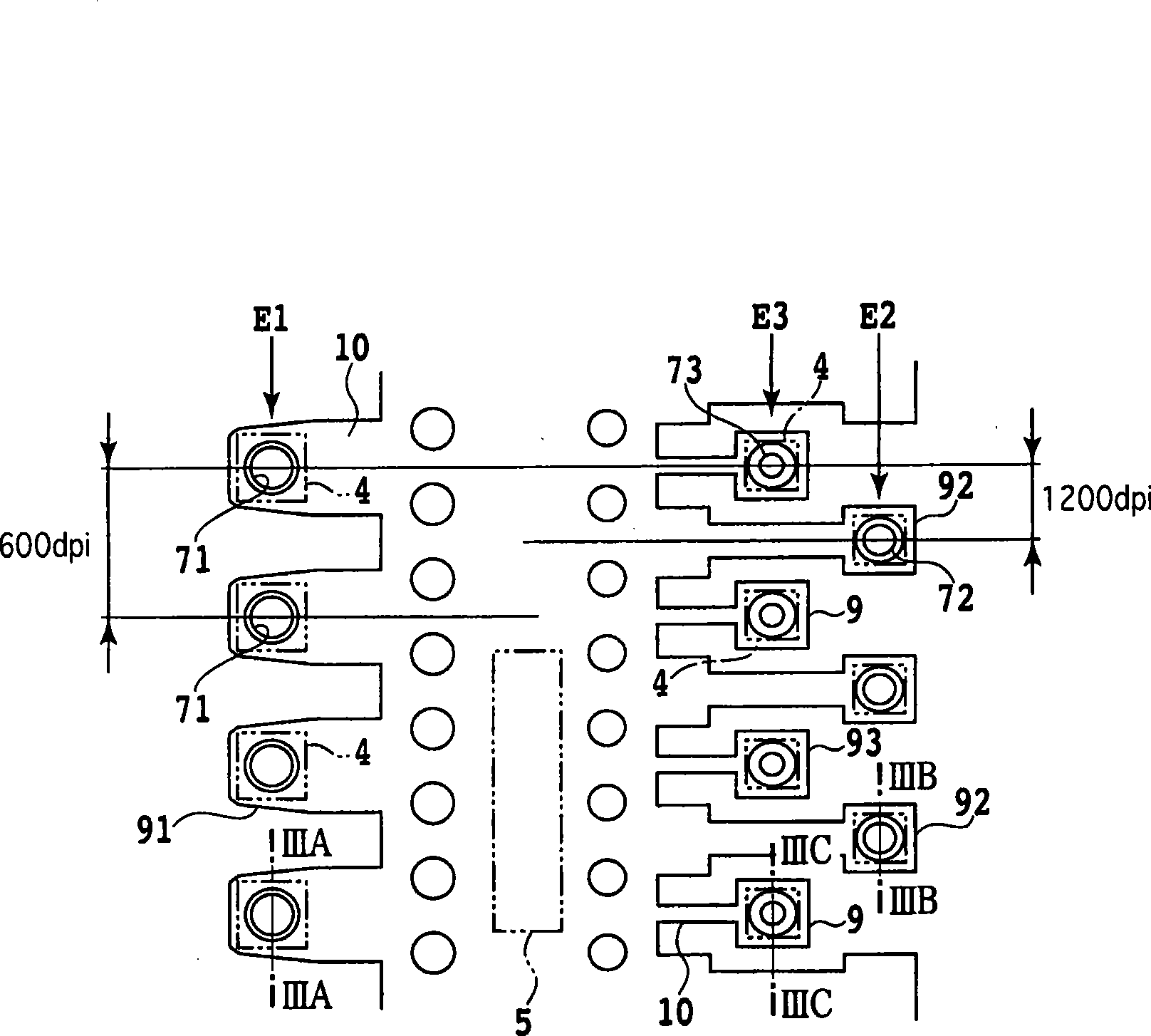
[0045] First, a first embodiment of the present invention will be described with reference to FIGS. 1 , 2 , 3A, 3B and 3C.
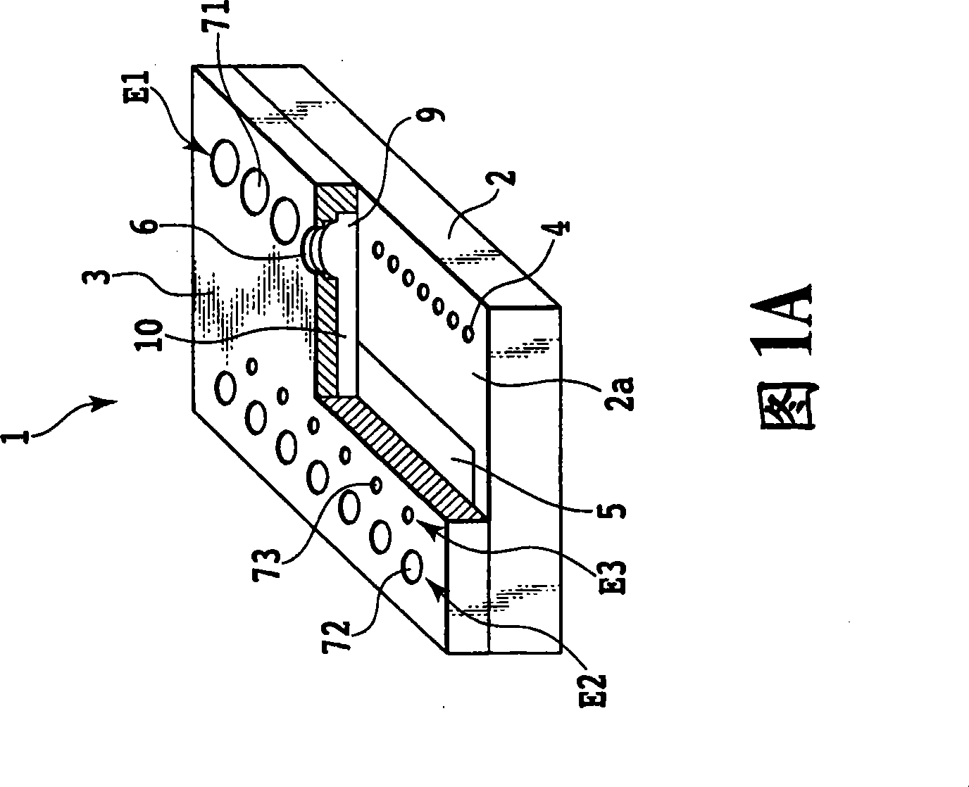
[0046] FIG. 1A is a partially cutaway perspective view schematically showing an inkjet printhead 1 according to a first embodiment. This inkjet printhead 1 includes an element substrate 2 having an electrothermal conversion element 4 as an ejection energy generating element, and a channel constituting substrate (orifice plate) 3 stacked on a main surface 2 a of the element substrate 2 .
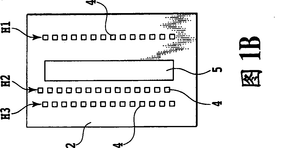
[0047] As shown in FIG. 1B , three printing element columns H1 , H2 , and H3 each composed of a plurality of electrothermal conversion elements 4 are arranged in parallel to each other on the element substrate 2 . The ink supply port 5 is formed between the first printing element column H1 and the second and third printing element columns H2 and H3.
[0048] A plurality of ejection port portions 6, a plurality of bubbling chambers 9, and a plurality of ink supply chann...
no. 2 approach
[0062] A second embodiment of the present invention will now be described.
[0063] Figure 4 is a bottom view of a part of the ejection port array in the inkjet printhead according to the second embodiment. Figure 4 The positional relationship between the foaming chamber 9 , the ink supply channel 10 , the electrothermal conversion element 4 , and the ejection ports 71 , 72 , and 73 is shown. In the second embodiment, the four ejection port columns E1 , E2 , E3 and E4 are arranged in parallel to each other. The first and second ejection port columns E1 and E2 are arranged on one side of the ink supply port 5 (on the left side in the drawing). The third and fourth ejection port columns E3 and E4 are arranged on the other side of the ink supply port 5 (in the figure, on the right side). As shown in FIG. 3A , each of the first and third ejection port rows E1 and E3 is constituted by a large ejection port 71 . As shown in FIG. 3B , the second ejection port row E2 is composed...
no. 3 approach
[0069] A third embodiment of the present invention will now be described.
[0070] In the second embodiment, all the injection openings are cylindrical. However, the injection port does not have to be cylindrical but may have other shapes. In the third embodiment, each injection port portion is formed to have an elliptical cross section.
[0071] Also in the third embodiment, the liquid amounts Va, Vb, and Vc of the large, medium, and small ink droplets are 2.8 ng, 1.4 ng, and 0.7 ng, respectively. The cross-sectional areas S1a, S2a and S3a of the injection ports are about 120um 2 、60um 2 and 30um 2 . The ratios of the opening area of the second injection port portion to the opening area of the injection port, ie, S1b / S1a, S2b / S2a, and S3b / S3a, were 3.1, 3.6, and 6.3, respectively.
[0072] Therefore, the magnitude relationship between the ratio of the opening area of the second injection port portion to the opening area of the first injection port portion is as ...
PUM
 Abstract
Description
Claims
Application Information
 - R&D
- Intellectual Property
- Life Sciences
- Materials
- Tech Scout
- Unparalleled Data Quality
- Higher Quality Content
- 60% Fewer Hallucinations
Browse by: Latest US Patents, China's latest patents, Technical Efficacy Thesaurus, Application Domain, Technology Topic, Popular Technical Reports.
© 2025 PatSnap. All rights reserved.Legal|Privacy policy|Modern Slavery Act Transparency Statement|Sitemap|About US| Contact US: help@patsnap.com


