Van-type semi-trailer

A semi-trailer and fixing hole technology, applied in the direction of tractor-trailer combination, motor vehicle, vehicle parts, etc., can solve the problem of inconvenient fixing of van semi-trailer, and achieve the effect of convenient removal

Inactive Publication Date: 2009-03-04
CHINA INTERNATIONAL MARINE CONTAINERS (GROUP) CO LTD
2 Cites 0 Cited by

AI-Extracted Technical Summary

Problems solved by technology

[0005] The technical problem to be solved by the present invention is to provide a vehicle that is easy to fix and disassemble during transportation without changing ...

Method used

[0037] As shown in FIG. 7, in the third embodiment of the present invention, the shape of the fixing hole 110 is a cam shape, including a small diameter portion and a large diameter portion, and the small diameter portion is inclined upward. The shape of the end of the connecting rod 120 is the same as that of the fixing hole 110 , that is, a small diameter portion extends from the end of the connecting rod 120 . During installation, the end of the connecting rod 120 is aligned with the fixing hole 11...

Abstract

The invention relates to a van semi-trailer comprising a chassis; the chassis comprises two longitudinal beams, a bottom beam which is positioned between the longitudinal beams, and slide track beams which are connected with the bottom beam, and a fixed hole for fastening and fixing is formed on the bottom beam. The fixed hole can be connected with a connecting rod. The fixed holes are formed on the two slide track beams, and the connecting rods which are connected with a fastening and fixing device penetrate the fixed holes. When in transportation, the connecting rods are utilized to connect a rope or a strapping tape for fastening, and then the van semi-trailer can be fastened and fixed on a transport tool. When the van semi-trailer is transported to the destination, the rope or the strapping tape for fastening is untied, then the van semi-trailer can be detached, and the connecting rods can be left on the van semi-trailer and can also be detached. The connecting rods not only can facilitate the detachment, but also can not change the main chassis structure of the prior van semi-trailer or affect the use of the semi-trailer.

Application Domain

UnderstructuresTractor-trailer combinations +2

Technology Topic

EngineeringStrapping +4

Image

  • Van-type semi-trailer
  • Van-type semi-trailer
  • Van-type semi-trailer

Examples

  • Experimental program(1)

Example Embodiment

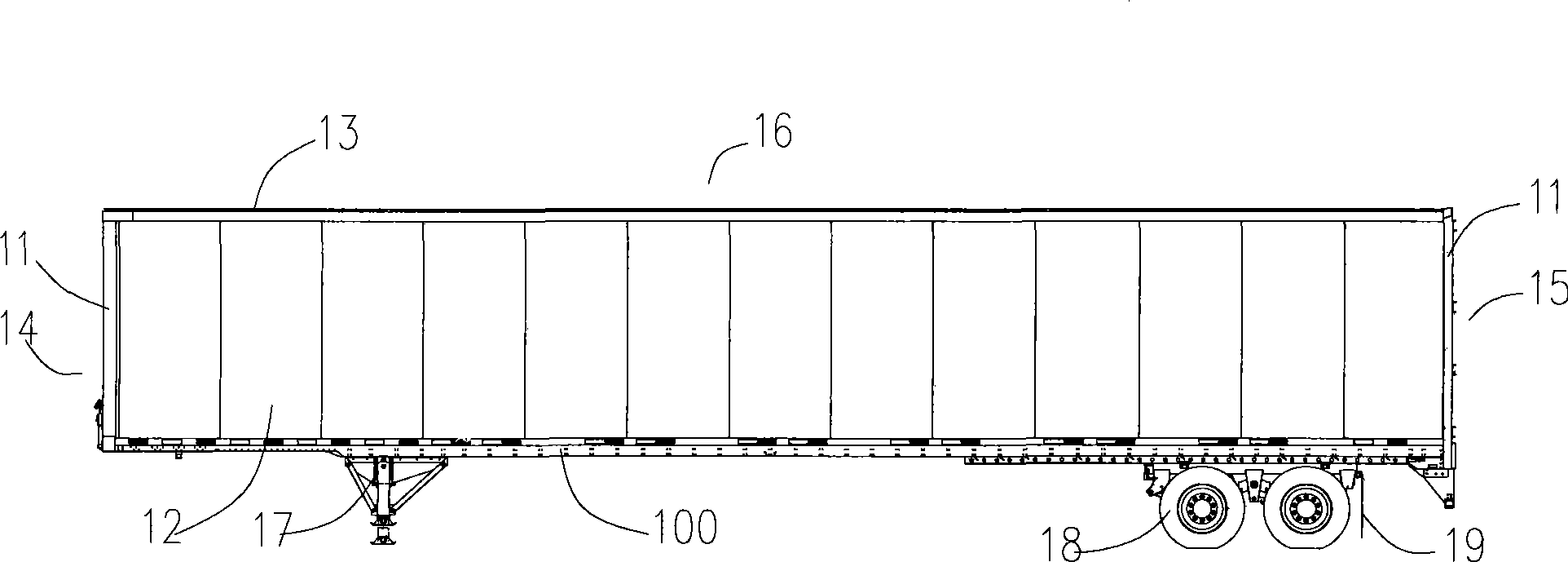
[0032] In the present invention, the van-type semi-trailer includes an underframe, on which parts such as uprights, side panels, and top plates are arranged, and these components together with the underframe constitute a box body. 2-3 pairs of tires are arranged at one end of the bottom frame, and legs are arranged at the other end to support the box body.
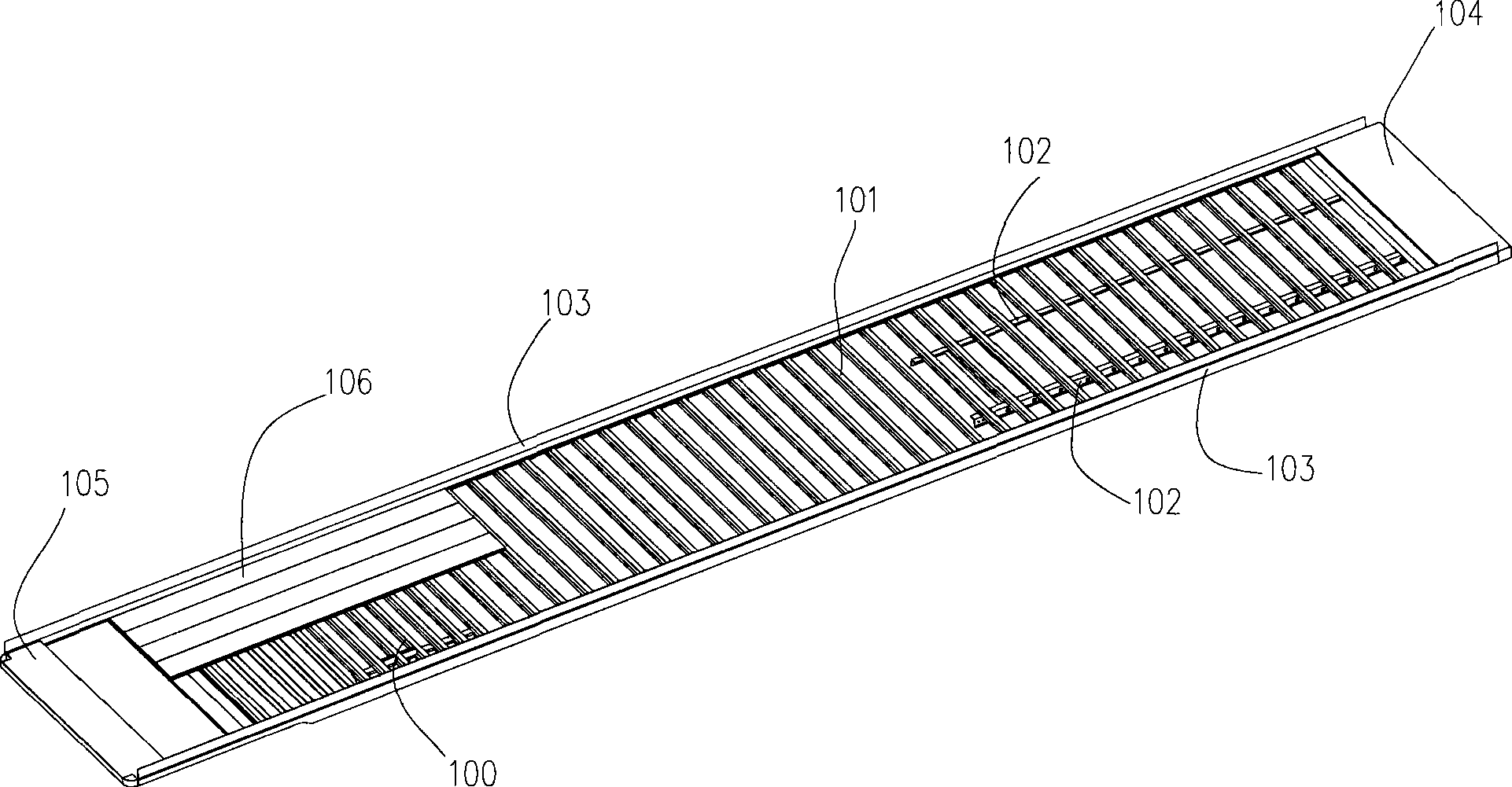
[0033] like figure 2 As shown, the underframe 100 includes two longitudinal beams 103, several bottom cross beams 101 between the two longitudinal beams 103, two slide rail beams 102 connected to the bottom cross beams 101 and used to connect supporting tires, arranged on two longitudinal beams 103 The traction plate 105 at one end of the beam 103 , the rear end beam 104 arranged at the other end of the two longitudinal beams and the wooden floor 106 above the bottom cross beam 101 .
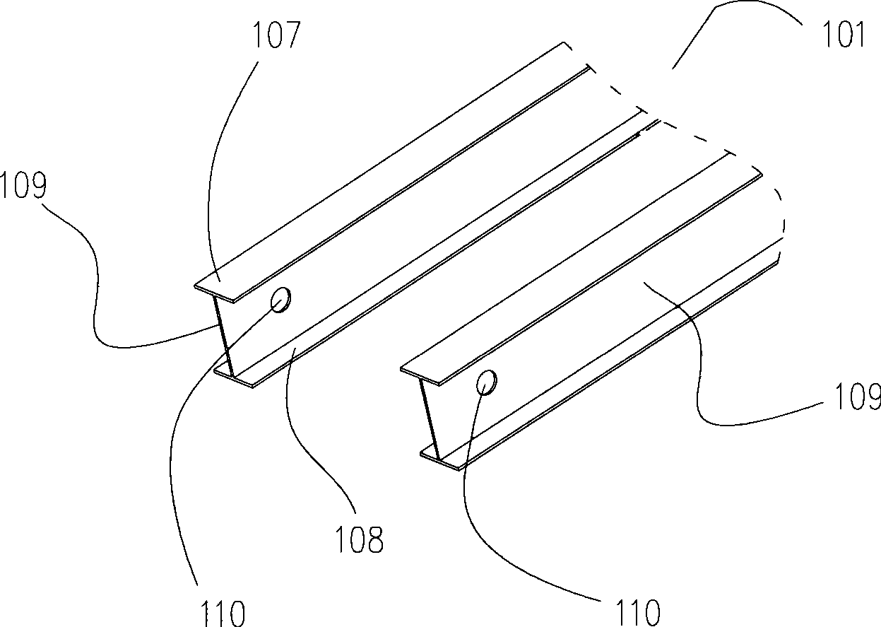
[0034] Considering that the bottom cross beam 101 of the chassis 100 can bear a relatively large load, therefore, when designing and manufacturing the van type semi-trailer, a fixing device is provided on the bottom cross beam 101 in advance. like image 3 , 4 As shown, in the first embodiment of the present invention, the bottom beam 101 is "I" shaped, including a top plate 107, a bottom plate 108, and a web 109 connected between them. The fixing device of the car body includes a fixing hole 110 . The fixing holes 110 are arranged at both ends of the webs 109 of two adjacent bottom beams 101 , and may be circular holes, oval holes, rectangular holes or polygonal holes. After the van-type semi-trailer is loaded onto the vehicle as a whole, a rope or a binding strap can be used to pass through the fixing hole 110 to fix the van-type semi-trailer.
[0035] like Figure 4 As shown, the securing device may also include a connecting rod 120 . One end of the connecting rod 120 passes through the fixing hole 110 on the bottom cross beam 101 , and the other end passes through the fixing hole 110 on the adjacent bottom cross beam 101 , so that it is fixedly erected between the two bottom cross beams 101 . The connecting rod 120 can be fixed by means of welding, riveting, threading and the like. The fixing holes 110 at both ends of the connecting rod 120 are symmetrical in the longitudinal direction of the car body to maintain balance. After the van-type semi-trailer is loaded onto the vehicle as a whole, the van-type semi-trailer can be fastened to the transport through the connecting rod 120 .
[0036] In the above embodiments, the connecting rod 120 can be fixedly connected between adjacent fixing holes 110 . It is also possible to directly weld the connecting rods 120 between adjacent bottom beams 101 . However, the connecting rod 120 can also be rotatably arranged in the fixing hole 110 , and the two ends of the connecting rod 120 are provided with anti-ejection structures. like Figure 5 and Image 6 As shown, in the second embodiment of the present invention, in order to prevent the connecting rod 120 from withdrawing from the fixing hole 110 during transportation, a notch 111 is provided on the circumference of the fixing hole 110 . A corresponding small boss 121 is provided at the end of the connecting rod 120 . During installation, after the boss 121 passes through the notch 111, the connecting rod 120 is assembled. Then rotate the connecting rod 120 at a certain angle along the axis of the connecting rod 120 to prevent it from exiting the fixing hole 110 .
[0037] like Figure 7 As shown, in the third embodiment of the present invention, the shape of the fixing hole 110 is a cam shape, including a small diameter portion and a large diameter portion, and the small diameter portion is inclined upward. The shape of the end of the connecting rod 120 is the same as that of the fixing hole 110 , that is, a small diameter portion extends from the end of the connecting rod 120 . During installation, the end of the connecting rod 120 is aligned with the fixing hole 110, and the connecting rod 120 is assembled. Under the action of gravity, the connecting rod 120 will slide into the large-diameter portion of the fixing hole 110 and rotate so that the small-diameter portion of the connecting rod 120 faces downward to maintain balance. Although the connecting rod 120 is a movable connection, because the end of the connecting rod 120 has a small-diameter part that prevents it from withdrawing, it can also ensure the safety of the van semi-trailer during transportation.
[0038] like Figure 8 As shown, in the fourth embodiment of the present invention, in order to prevent the connecting rod 120 from coming out of the fixing hole 110, the end of the connecting rod 120 can be threaded, and after the connecting rod 120 is assembled into the fixing hole 110, the connecting rod The end of 120 is screwed on nut 122 and gets final product. Holes can also be set at both ends of the connecting rod 120, and after being assembled, pins can be inserted into the holes for fixing.
[0039] In the above four embodiments, the fixing devices are arranged on the bottom beam 101 of the bottom frame 100 , which does not change the main structure of the bottom frame 100 . like Figure 12 and Figure 13 As shown, when the van semi-trailer is loaded on the vehicle as a whole, the connecting rod 120 can be tied with a rope or a strap 32 to fix the van semi-trailer.
[0040] In addition, the fixing device can also be arranged on the slide rail beam 102 of the chassis 100 for supporting the wheels, which utilizes the holes inherent in the slide rail beam 102 . After the van-type semi-trailer is loaded onto the vehicle as a whole, a rope or a binding strap can be used to pass through the fixing hole 110 to fix the van-type semi-trailer. can also be like Figure 9 As shown, in the fifth embodiment of the present invention, the slide rail beams 102 have fixing holes 131 , and the connecting rods 130 pass through the fixing holes 131 of two adjacent slide rail beams 102 . At the end of the connecting rod 120, a connecting hole 132 is provided. like Figure 12 and Figure 14 As shown, after the van-type semi-trailer is loaded onto the vehicle 31 as a whole, a rope or a binding strap 32 can be used to pass through the connecting hole 132 , thereby fastening the van-type semi-trailer to the fixing ring 33 of the vehicle 31 .
[0041] like Figure 10 and Figure 11 As shown, in the sixth embodiment of the present invention, the connecting rod is not integral. In the fixing holes 131 of adjacent slide rail beams 102 , connecting rods 140 are arranged symmetrically. One end of the connecting rod 140 has a limit block 141 , and the other end has a connecting hole 142 . The diameter of the limiting block 141 is larger than that of the fixing hole 131 to prevent the connecting rod 140 from coming out. During transportation, the van semi-trailer can be fastened to the transportation tool by passing through the connecting hole 142 with a rope or a binding strap.
[0042] When the van semi-trailer is transported to the destination, the van semi-trailer can be unloaded by untiing the tied ropes or straps, and the connecting rod can be left on the van semi-trailer. You can also turn the connecting rod to remove it. The fixing device of the invention is convenient to dismantle, and will not change the underframe structure of the current van-type semi-trailer, and will not affect the use of the semi-trailer.

PUM

no PUM

Description & Claims & Application Information

We can also present the details of the Description, Claims and Application information to help users get a comprehensive understanding of the technical details of the patent, such as background art, summary of invention, brief description of drawings, description of embodiments, and other original content. On the other hand, users can also determine the specific scope of protection of the technology through the list of claims; as well as understand the changes in the life cycle of the technology with the presentation of the patent timeline. Login to view more.

Similar technology patents

Device and method of melting polysilicon powder by electron beam

InactiveCN104402000Aeasy to removeShorten smelting time
Owner:DALIAN UNIV OF TECH

Fixed-point cleaning machine for fabric

Owner:上海仕操洗涤有限公司

External auditory canal cleaning tool

PendingCN108420602ADecreased adhesionEasy to remove
Owner:翟一舟

Classification and recommendation of technical efficacy words

  • Easy to remove

Ocean fishing vessel propeller

ActiveCN104828229AIncrease cutting powereasy to remove
Owner:ZHOUSHAN WONDERFUL MARINE DESIGN CO LTD
Why Eureka
Try Eureka