Cabinet air conditioner

An air conditioner, cabinet type technology, applied in the field of fixed structure of the air intake grille of the indoor unit of the cabinet type air conditioner

Inactive Publication Date: 2009-03-04
LG ELECTRONICS (TIANJIN) APPLIANCES CO LTD
View PDF0 Cites 2 Cited by
  • Summary
  • Abstract
  • Description
  • Claims
  • Application Information

AI Technical Summary

Problems solved by technology

[0004] The technical problem to be solved by the present invention is to overcome the disadvantages of the prior art, to install spring pieces and spring roller clips on the air inlet grille and the air inlet frame respectively, so that the air inlet grille can be installed on the air conditioner body conveniently and firmly.

Method used


Image

  • Cabinet air conditioner
  • Cabinet air conditioner

Examples


Embodiment Construction

[0011] The working principle of the cabinet-type air conditioner of the present invention is the same as that of the prior art, and will not be repeated here.

[0012] The present invention will be described in further detail below in conjunction with accompanying drawing and specific embodiment.

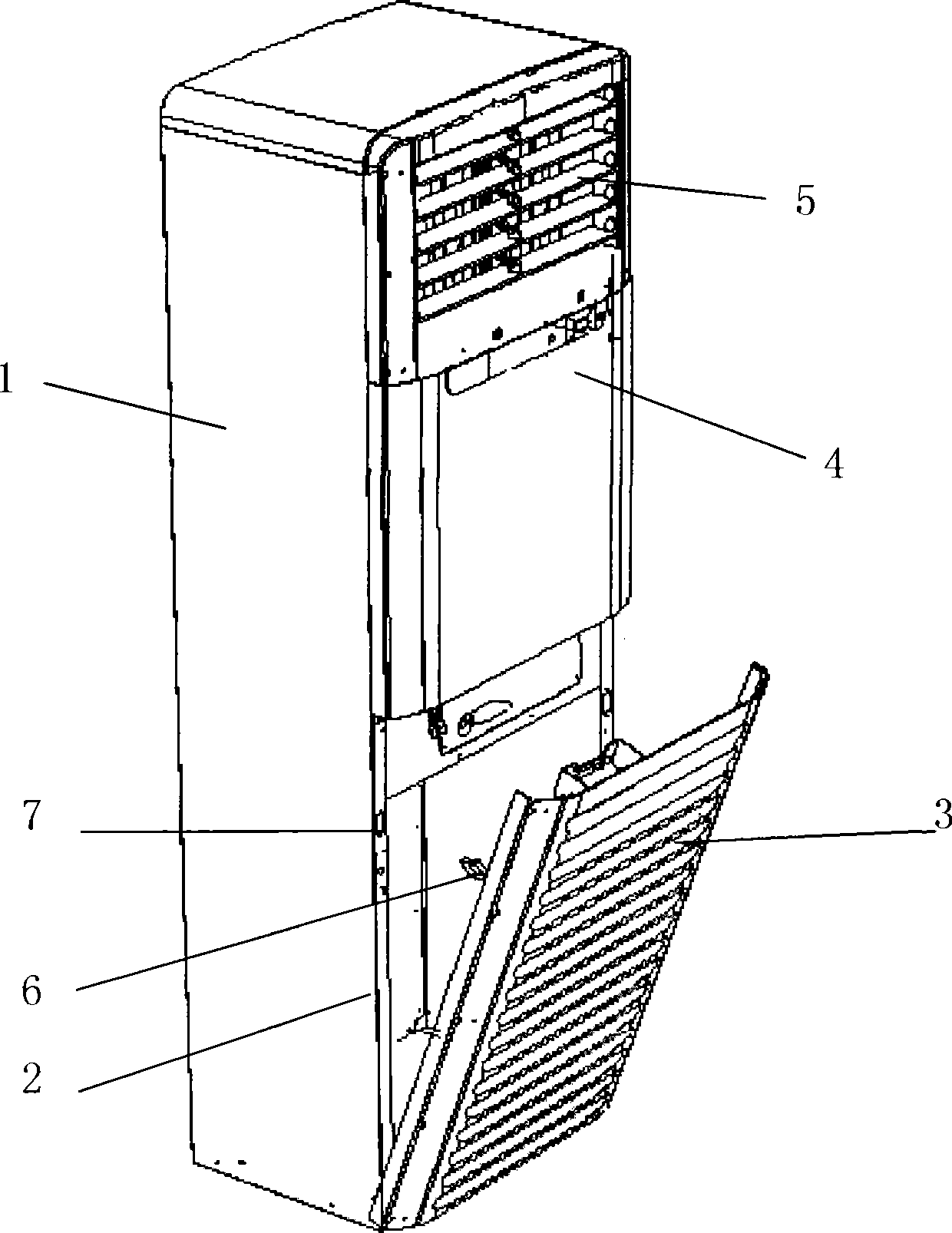
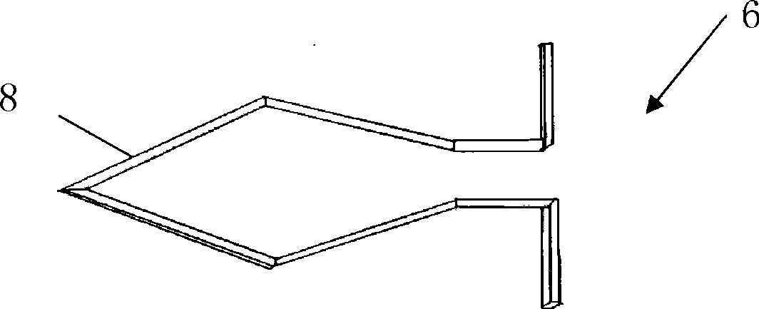
[0013] figure 1 It is a three-dimensional schematic diagram of the installation of the air intake grille in the cabinet air conditioner of the present invention, figure 2 It is a front view of the spring leaf arranged on the air intake grille of the grille air conditioner of the present invention.

[0014] Such as figure 1 As shown, the cabinet-type air conditioner of the present invention includes: an air conditioner body 1, an inlet grill frame 2, an inlet grill 3, a control panel 4, an outlet grill 5, a spring roller clip 7, and a spring leaf 6, The spring roller clip 7 is arranged on the intake grill frame, and the spring sheet 6 is arranged on the intake grill corresponding...


PUM


Abstract

The invention discloses a cabinet type air conditioner, which comprises an air conditioner body, an air inlet grille skeleton, an air inlet grille, a control panel and a ventilation grille, wherein, each side of the air inlet grille skeleton is provided with a spring roller clip; each side of the air inlet grille is provided with a spring plate corresponding to each spring roller clip; the spring plates are inserted into the spring roller clips. The spring plates and the spring roller clips are used to fix conveniently the air inlet grille on the air conditioner body.

Description

technical field [0001] The invention relates to a cabinet type air conditioner, in particular to a fixing structure for an air inlet grill of an indoor unit of the cabinet type air conditioner. Background technique [0002] An air conditioner is a device that makes its internal refrigerant undergo a refrigeration or heating cycle consisting of a compression process, condensation process, expansion process, and evaporation process. When the air conditioner is in the refrigeration cycle, the refrigerant compressed by the compressor and turned into a high-temperature and high-pressure state can flow to the condenser under the guidance of the four-way valve, and dissipate heat to the outside in the condenser, and then significantly reduce when flowing through the expansion valve. Its temperature and pressure, then the low-temperature, low-pressure refrigerant absorbs heat as it flows through the evaporator, and finally passes through the liquid storage tank and flows back into t...

Claims


Application Information

Patent Timeline
Patent Type & Authority Applications(China)
IPC IPC(8): F24F13/20F24F13/08
Inventor 李彬
Owner LG ELECTRONICS (TIANJIN) APPLIANCES CO LTD
Why Eureka
Try Eureka