Banknote case for automatic counter machine supporting stored banknote to be fetched by drawing person instantly

A banknote box, automatic technology, applied in the direction of coinless or similar appliances, complete banking systems, coin accepting devices, etc., can solve the problems of banknotes being messed up, time-consuming, inconvenient, etc., to increase the efficiency of use , the effect of saving manpower and time, and reducing operating costs

Inactive Publication Date: 2009-03-04
黄金富
View PDF0 Cites 6 Cited by
  • Summary
  • Abstract
  • Description
  • Claims
  • Application Information

AI Technical Summary

Problems solved by technology

[0002] At present, the general automatic deposit and withdrawal machine (also known as automatic teller machine or cash withdrawal machine) is equipped with independent deposit cash box and withdrawal cash box. The deposit cash box is only for depositing banknotes, and the withdrawal cash box is only for withdrawing banknotes , so the banknotes deposited cannot be withdrawn immediately by the withdrawer, but the bank will recycle and count the deposit cash box, so that it will take time to recover and count the deposited banknotes, and it is very inconvenient to replenish the cash withdrawal box of
The general withdrawal cash box requires the banknotes in the box to be neatly placed, so that the banknotes can be output accurately, but the banknotes stored in the general deposit cash box cannot be neatly stacked together, and the deposited banknotes are often in a mess. , the problem we are facing is that we cannot effectively stack the deposited banknotes in an appropriate position, which is a problem that needs to be solved

Method used


Image

  • Banknote case for automatic counter machine supporting stored banknote to be fetched by drawing person instantly
  • Banknote case for automatic counter machine supporting stored banknote to be fetched by drawing person instantly
  • Banknote case for automatic counter machine supporting stored banknote to be fetched by drawing person instantly

Examples


Embodiment Construction

[0016] The automatic banknote box of the present invention will be described in further detail below in conjunction with the accompanying drawings.

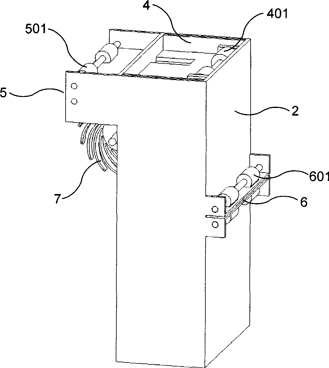
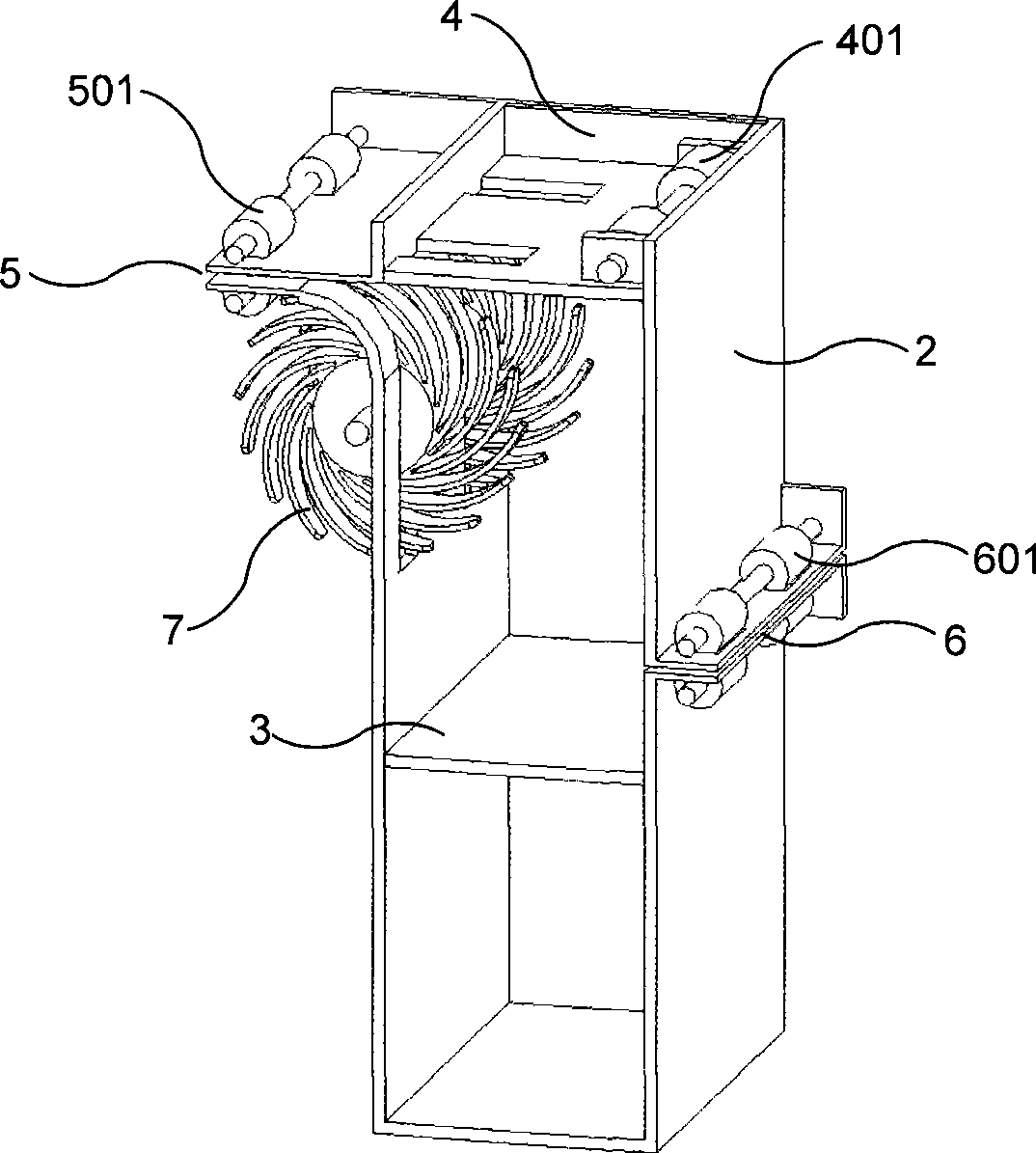
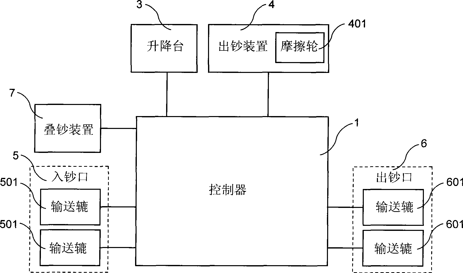
[0017] refer to Figure 1 to Figure 3 , figure 1 It is a visualized three-dimensional explanatory diagram of the automatic cash box of the present invention, figure 2 It is an explanatory diagram of the visualized three-dimensional internal structure of the automatic banknote box of the present invention, image 3 It is a block explanatory diagram of the structure of the automatic cash box of the present invention, Figure 1 to Figure 3 The automatic banknote box shown in includes a controller (1), a housing (2), a lifting platform (3), a banknote output device (4), a banknote input port (5), a banknote output port (6), and a banknote stacking device (7), wherein, described controller (1) is provided with CPU and the circuit of controlling each component, and with lifting table (3), banknote output device (4), banknote inlet ...


PUM


Abstract

The invention discloses an automatic banknote case that is used for automatic teller machines, provides the banknote depositing and withdrawing functions, and the essential structure thereof comprises a controller (1), an outer shell (2), an elevating platform (3), a banknote outputting device (4), a banknote inlet (5), a banknote outlet (6) and a banknote overlaying device (7). When depositing banknotes (11), the deposited banknotes (11) pass through the banknote inlet (5) and the banknote overlaying device (7), and are overlaid on the elevating platform (3); when withdrawing the banknotes (11), the automatic banknote case moves and leads the banknote outputting device (4) to aim at the position of the banknote outlet (6), and the banknotes (11) on the elevating platform (3) are output from the automatic banknote case through the banknote outputting device (4) and the banknote outlet (6). The automatic teller machines with the automatic banknote case installed can lead deposited banknotes to be withdrawn by withdrawers in time, thus improving the use efficiency of the banknotes (11), reducing the banknote replenishing time of the banknote case for banks, and consequently lowering the running cost of the automatic teller machines.

Description

【Technical field】 [0001] The invention relates to a bank machine, in particular to an automatic cash box for an automatic deposit and withdrawal machine. 【Background technique】 [0002] At present, the general automatic deposit and withdrawal machine (also known as automatic teller machine or cash withdrawal machine) is equipped with independent deposit cash box and withdrawal cash box. The deposit cash box is only for depositing banknotes, and the withdrawal cash box is only for withdrawing banknotes , so the banknotes deposited cannot be withdrawn immediately by the withdrawer, but the bank will recycle and count the deposit cash box, so that it will take time to recover and count the deposited banknotes, and it is very inconvenient to replenish the cash withdrawal box of. The general withdrawal cash box requires the banknotes in the box to be neatly placed, so that the banknotes can be output accurately, but the banknotes stored in the general deposit cash box cannot be ...

Claims


Application Information

Patent Timeline
Patent Type & Authority Applications(China)
IPC IPC(8): G07F19/00G07D11/00
Inventor 黄金富
Owner 黄金富
Why Eureka
Try Eureka