
Device for measuring the angle between far sight and near sight on a patient wearing spectacles

A device and angle technology, applied in the direction of eye testing equipment, glasses/protective glasses, glasses/goggles, etc., can solve the problems of inaccurate values, the position of the patient cannot be accurately corresponded, and the patient cannot be accurately known.

Inactive Publication Date: 2009-03-04
ACEP FRANCE
View PDF0 Cites 8 Cited by
  • Summary
  • Abstract
  • Description
  • Claims
  • Application Information

AI Technical Summary

Problems solved by technology

In fact, an optician who asks a patient to gaze at a distance does not know exactly what the patient is looking at
The patient's gaze may be drawn to specific objects, so the patient's position does not correspond exactly to that of hypermetropia
This leads to the inability to determine the proper position of the glasses for farsightedness, which makes the value of the distance d imprecise
This causes the patient to be forced to adjust (move) the glasses when transitioning from hyperopia to myopia or vice versa, causing inconvenience

Method used


Image

  • Device for measuring the angle between far sight and near sight on a patient wearing spectacles
  • Device for measuring the angle between far sight and near sight on a patient wearing spectacles
  • Device for measuring the angle between far sight and near sight on a patient wearing spectacles

Examples


Embodiment Construction

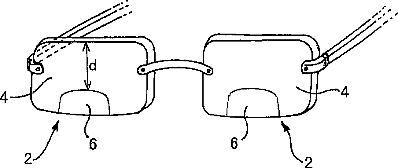
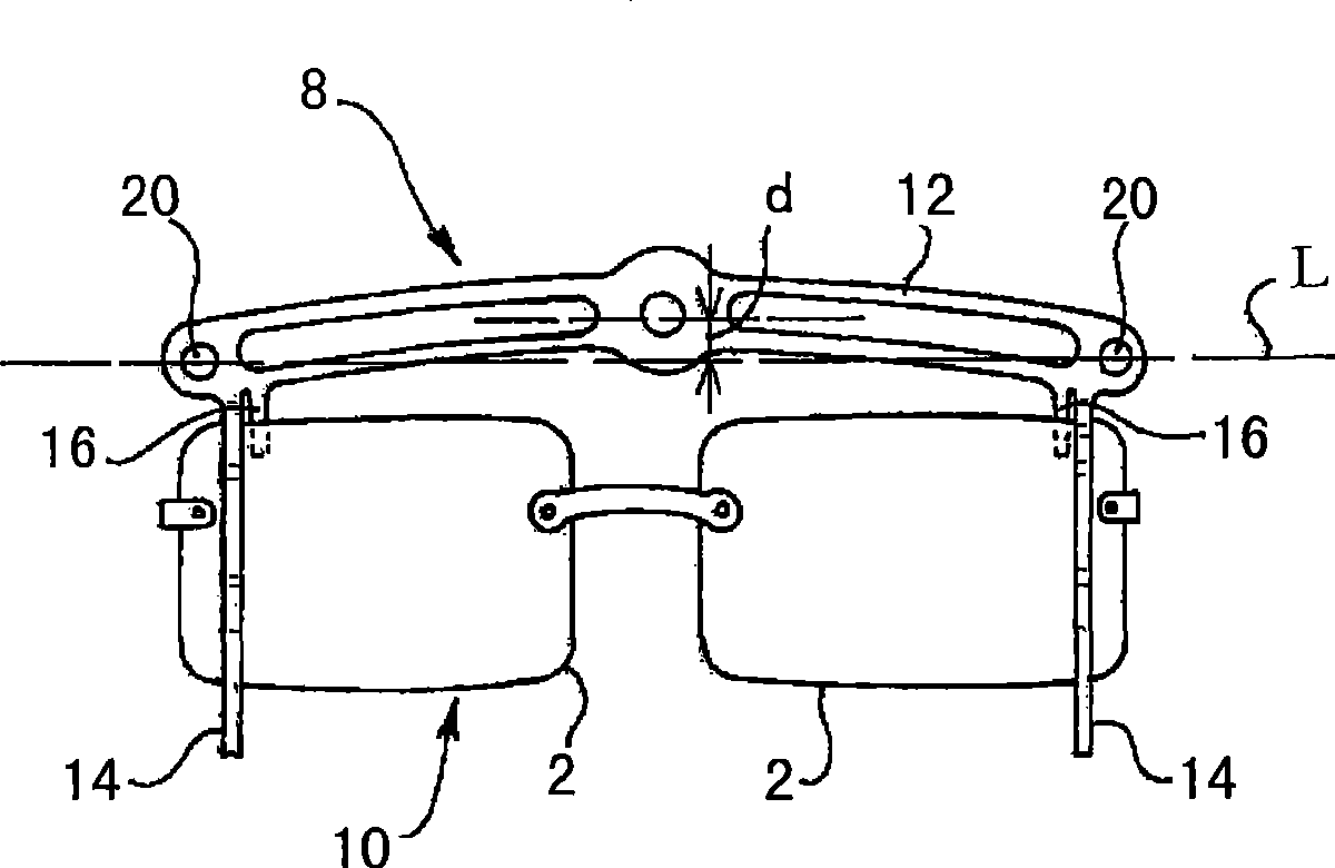
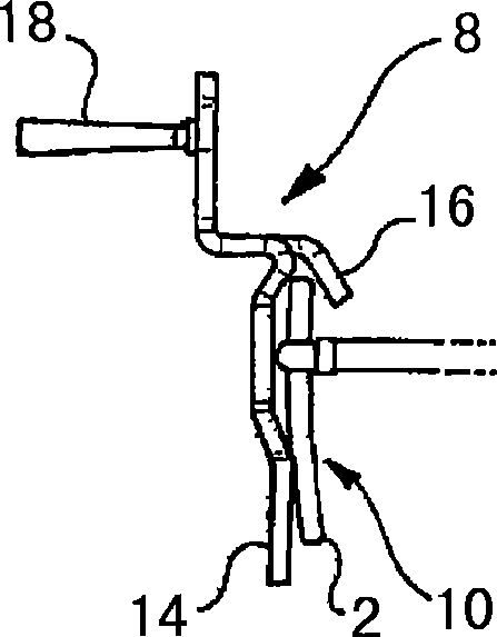
[0019] Figure 2a and Figure 2b Orientation assembly 8 is shown mounted on eyeglasses 10 . This directional assembly comprises an approximately horizontal beam 12, the ends of the beam 12 are respectively provided with a first branch 14 and a second branch 16, and the front of the correction lens 2 is supported against the first branch 14 , the back of the correction lens is supported against the second branch 16 . The orientation assembly includes at least one reference marker 18 . The orientation of reference mark 18 is recorded and determined by a measuring device. The difference in the position of the patient's head due to the different orientations of the patient's head for farsightedness and nearsightedness allows the optician to precisely determine for each patient the appropriate distance d (see figure 1 ) value.

[0020] Such as Figure 2a As shown, the orientation assembly may include additional reference marks, such as reference mark 20, in order to verify th...


PUM


Abstract

The invention relates to a device for measuring the angle delta formed between a first position, corresponding to far sight, of a patient wearing a pair of spectacles, and a second position, corresponding to near sight, said device comprising: a recording means (22) for recording the orientation of the pair of spectacles in each of the two positions, and a processing means (30) for determining the angle delta as a function of said orientations, said device being characterized in that it comprises a visual reference element (26) for defining the attitude of the patient in far sight.

Description

technical field [0001] The invention relates to a device for measuring an angle Δ formed between a first position corresponding to the position of a patient wearing spectacles when farsighted, and a second position corresponding to the position of a patient wearing spectacles position when nearsighted. Background technique [0002] In the field of eyewear business, various methods and devices are known to determine the physiological parameters of a patient in order to obtain suitable eyeglass frames. Some of these devices can automatically record measurements by cameras, and can be determined to obtain suitable measurements by the means used to process the images obtained. By making these measurements, the optician can therefore configure a corrective lens that matches the patient's needs. [0003] The present invention relates to a corrective lens that allows both hypermetropia and myopia. figure 1 A pair of spectacles including such a corrective lens is shown in . Each...

Claims


Application Information

Patent Timeline
IPC IPC(8): A61B3/00G02C13/00
CPCA61B3/024G02C13/003A61B3/00G02C13/00
Inventor 让-菲利普·萨伊格
Owner ACEP FRANCE
Learn More