Pneumatic tool with wear resistance

A pneumatic tool, wear resistance technology, applied in the direction of manufacturing tools, portable motorized devices, etc., can solve problems such as wear, cylinder component failure, heat generation, etc., to achieve the effect of improving work efficiency and improving the life of pneumatic tools

Inactive Publication Date: 2010-09-29
HYPHONE MASCH IND CO LTD
View PDF7 Cites 0 Cited by
  • Summary
  • Abstract
  • Description
  • Claims
  • Application Information

AI Technical Summary

Problems solved by technology

[0007] Aiming at the deficiencies of the prior art, the object of the present invention is to provide a wear-resistant pneumatic tool to solve the problem that the existing pneumatic tool generates heat and severe wear due to the mutual friction between the rotor and the cover, which makes the cylinder assembly invalid question

Method used


Image

  • Pneumatic tool with wear resistance
  • Pneumatic tool with wear resistance
  • Pneumatic tool with wear resistance

Examples


Embodiment Construction

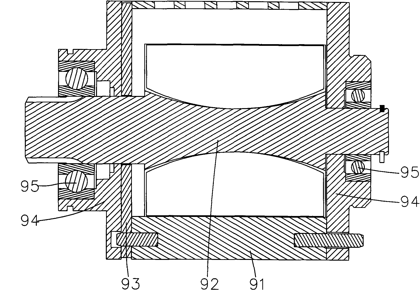
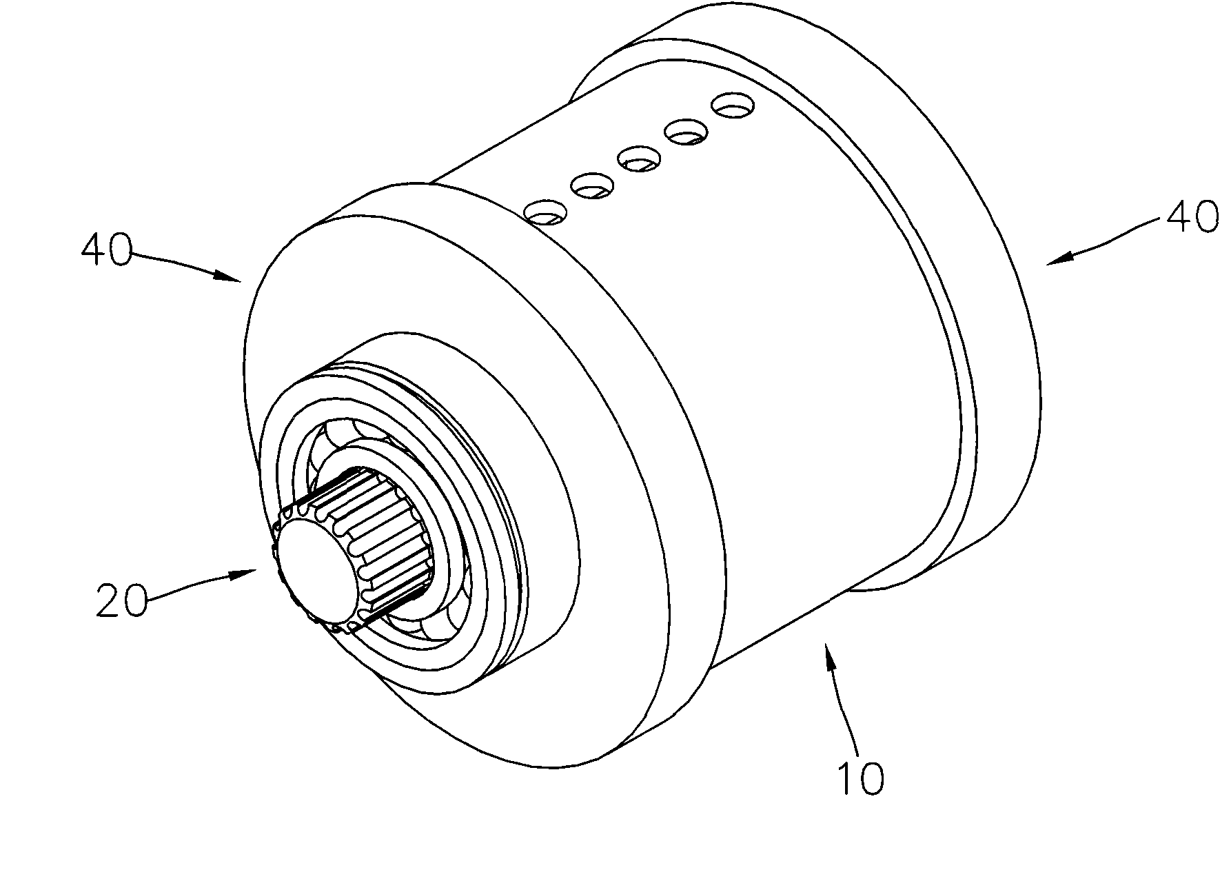
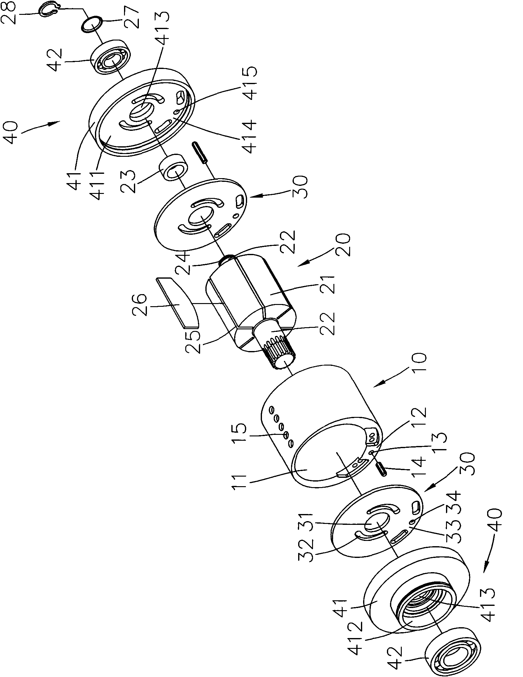
[0025] refer to figure 2 and image 3 , is the three-dimensional appearance view and three-dimensional exploded view of the first embodiment of the wear-resistant pneumatic tool of the present invention. The wear-resistant pneumatic tool of the present invention includes a cylinder 10 , a rotor 20 , two gaskets 30 and two outer cover assemblies 40 .

[0026] The cylinder 10 includes an eccentric cavity 11, one end on both sides of the cylinder 10 is a fixed portion 12, the fixed portion 12 is arranged at the thicker end of the cylinder 10, the fixed portion 12 on both sides is provided with at least one fixed hole 13, At the same time a pin 14 is inserted in the fixing hole 13 . Opposite to the other end of the fixing hole 13 , several air holes 15 are arranged radially on the outer peripheral surface of the cylinder 10 .

[0027] The rotor 20 is accommodated in the cavity 11 of the cylinder 10. The rotor 20 includes a body 21 and an axis 22 extending from two sides of the...


PUM


Abstract

The present invention relates to a pneumatic tool with wearing resistance. The pneumatic tool comprises a rotor penetrating a cylinder, two gaskets which respectively covers at the two sides of the cylinder and two external cover components which respectively comprise an external cover and a bearing to ensure that the external cover covers over the gaskets, and the axle center of the rotor penetrates a punch hole and penetrates the bearing, wherein, the axle center of the rotor penetrates a jacket, the jacket is arranged in the punch holes of the gaskets and the punch hole of the external cover, one end of the jacket presses and resists against the bearing, and the other end is exposed at the gaskets convexly to press and resist against the body of the rotor, so as to keep the distance between the rotor and the gaskets.

Description

technical field [0001] The invention relates to a pneumatic tool, in particular to a wear-resistant pneumatic tool, which can increase the service life. Background technique [0002] refer to figure 1 , is a schematic cross-sectional view of an existing pneumatic tool. Existing pneumatic tool comprises a cylinder 91, is provided with a rotor 92 inside, and the front end of cylinder 91 is covered with a pad 93, and the outside of pad 93 and the other end of cylinder 91 are respectively covered with a lid 94, and two lids 94 and A bearing 95 is arranged between the rotors 92 respectively. When the rotor 92 is confined in the cylinder 91 and the rotor 92 rotates, the cylinder 91 , the spacer 93 and the cover 94 do not rotate. [0003] There is a deficiency in the above-mentioned pneumatic tools. Pneumatic tools often work out of the ideal state. When the bearing and the rotor are tightly fitted, during the assembly process, the gap between the cover and the rotor will be made...

Claims


Application Information

Patent Timeline
Patent Type & Authority Patents(China)
IPC IPC(8): B25F5/00
Inventor 陈丽珍
Owner HYPHONE MASCH IND CO LTD
Why Eureka
Try Eureka