Pivot hinge device with torsion adjustable

A door shaft and torsion technology, which is applied to door/window accessories, buildings, wing leaf openers, etc., can solve the problems of time-consuming and inconvenient adjustment, short service life, and limited adjustment amount, etc.

Inactive Publication Date: 2009-03-11
陈 建竹
View PDF0 Cites 28 Cited by
  • Summary
  • Abstract
  • Description
  • Claims
  • Application Information

AI Technical Summary

Problems solved by technology

[0003] The above-mentioned hinge device 10 does have the effect of torque recovery, but its usability is still lacking. The existing known hinge device 10 uses the adjustment pin 18 to abut against the inner wall of the chute 122 and then adjusts the sleeve 17 Just begin to twist to torsion spring 16 and produce torsion force, yet this chute 122 can only open a short distance, so the adjustment amount of torsion force size is quite limited, and hinge device 10 is to insert the plug-in screw connection of different positions by adjusting pin 18. Adjustment is made in the hole 172. This kind of plug-in adjustment is time-consuming and inconvenient. In addition, the first and second seat plates 11, 12 are overlapped and combined, and a washer 13 is used for running-in in the middle. The plate 11 is pressed against the washer 13 with the entire surface contact. When the first seat plate 11 is installed on a heavy door panel, the bearing weight will be transmitted to the torsion spring 16 through the mandrel 14 and cause heavy pressure damage. Therefore, use The service life is short, and the first and second seat plates 11 and 12 will also generate great frictional resistance when pivoting, resulting in the phenomenon that the opening and closing of the door is prone to jamming and unsmooth
[0004] This shows that the above-mentioned existing hinge device obviously still has inconvenience and defects in structure and use, and needs to be further improved urgently.
In order to solve the above-mentioned problems, the relevant manufacturers have tried their best to find a solution, but no suitable design has been developed for a long time, and the general products do not have an appropriate structure to solve the above-mentioned problems. This is obviously related. The problem that the industry is eager to solve

Method used


Image

  • Pivot hinge device with torsion adjustable
  • Pivot hinge device with torsion adjustable
  • Pivot hinge device with torsion adjustable

Examples


Embodiment Construction

[0040] In order to further explain the technical means and effects of the present invention to achieve the intended purpose of the invention, the specific implementation and structure of the door shaft hinge device with adjustable torsion according to the present invention will be described below in conjunction with the accompanying drawings and preferred embodiments. , features and their effects are described in detail below.

[0041] Regarding the foregoing and other technical contents, features and effects of the present invention, the present invention will be described in detail below in conjunction with the accompanying drawings and an embodiment, which will be clearly presented.

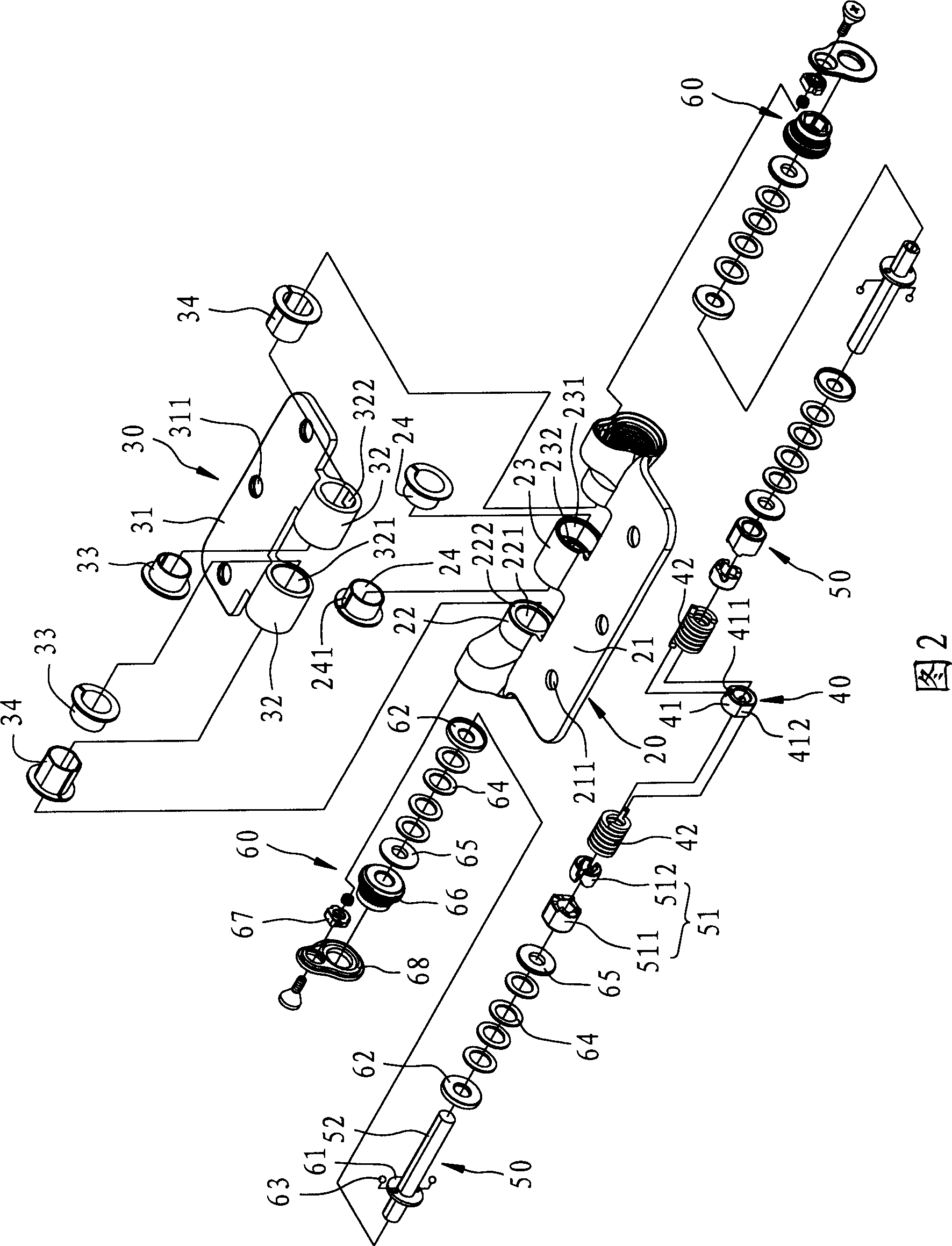
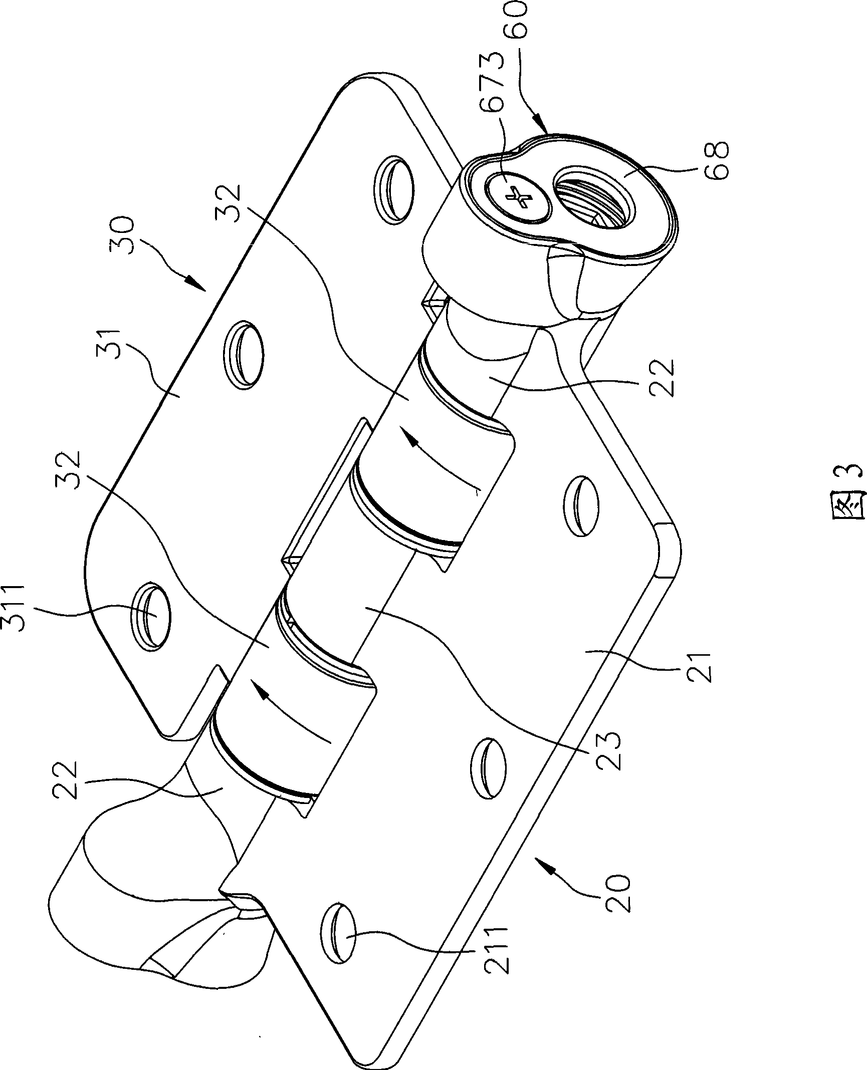
[0042] Please refer to Fig. 2, Fig. 3 and Fig. 4. Fig. 2 is an exploded perspective view of a preferred embodiment of the adjustable torsion door shaft hinge device of the present invention, illustrating that the present invention includes a set of first seat plate units, a set of A second sea...


PUM


Abstract

The invention relates to a door pivot hinge device capable of adjusting a torque force. The door pivot hinge device comprises a first base plate unit, a second base plate unit, a torque force providing unit, a torque force adjusting unit and a speed adjusting unit. The first base plate unit and the second base plate unit are embedded into each other and can revolve. The torque force providing unit has a torsion spring capable of leading a door sheet to produce a torque force. The torque force adjusting unit has a mandrel and a single cam set, wherein the mandrel can drive the torsion spring through the single cam set so as to adjust the torque force. The speed adjusting unit has a brake disc, a plurality of elastic elements and an adjusting element, wherein the adjusting element can pressthe elastic element so as to adjust the rotation speed. Therefore, the door pivot hinge device has the adjustable torque force, and smooth operation for door opening and closing , and is suitable forhigh load.

Description

technical field [0001] The present invention relates to a hinge device, in particular to a door hinge hinge with adjustable torque, high load-bearing capacity, and smooth operation for opening and closing doors, which is used for pivoting doors device. Background technique [0002] Generally, the door panel is usually installed and fixed on the door frame by a set of hinge devices, and the door panel can be opened and closed by rotating in the door frame through the hinge device. Please refer to figure 1 Shown is the exploded perspective view of the prior known hinge device. A known hinge device 10 with torque recovery function includes a first seat plate 11, a second seat plate 12, a washer 13, a mandrel 14, two fixing screws 15, A torsion spring 16, an adjustment sleeve 17 and an adjustment pin 18, the first and second seat plates 11, 12 are respectively installed on the door panel and the door frame (not shown), and a mutual Corresponding pivoting pipe parts 111, 121, ...

Claims


Application Information

Patent Timeline
Patent Type & Authority Applications(China)
IPC IPC(8): E05F1/12
Inventor 陈建竹
Owner 陈 建竹
Why Eureka
Try Eureka