Multi lateral compensation type high power density electromechanical energy convertor

A technology with high power density and electromechanical energy, applied in the direction of electromechanical devices, mechanical energy control, multi-output synchronous motors, etc., can solve the problems of not being able to be adjusted arbitrarily, restricting the application range of the system, and large voltage adjustment rate, etc., to achieve simple structure, high voltage The effect of low adjustment rate and high power density

Inactive Publication Date: 2010-04-14
HARBIN INST OF TECH
View PDF3 Cites 0 Cited by
  • Summary
  • Abstract
  • Description
  • Claims
  • Application Information

AI Technical Summary

Problems solved by technology

[0005] The invention solves the problem that the existing traditional flywheel energy storage system makes the output voltage adjustment rate of the generator large, and the DC bus voltage is determined by the power supply and cannot be adjusted arbitrarily, thereby limiting the application range of the system. A Multilateral Compensation High Power Density Electromechanical Energy Converter

Method used


Image

  • Multi lateral compensation type high power density electromechanical energy convertor
  • Multi lateral compensation type high power density electromechanical energy convertor
  • Multi lateral compensation type high power density electromechanical energy convertor

Examples


specific Embodiment approach 1

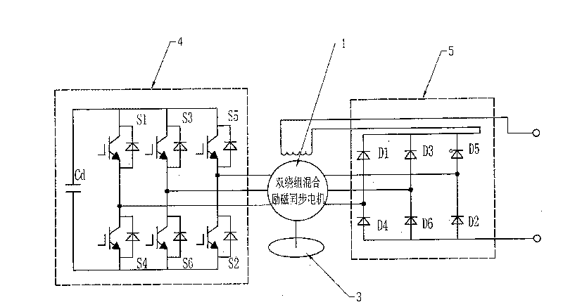
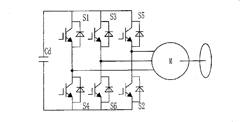
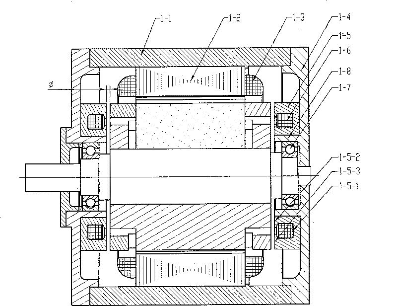
[0009] Specific implementation mode one: as Figure 1 to Figure 18 As shown, this embodiment is composed of a double-winding hybrid excitation synchronous motor 1, an inertial flywheel 3, an inverter 4 and a rectifier 5; -2. Two sets of armature windings 1-3, two end caps 1-4, two magnetic conducting rings 1-5 and two DC excitation windings 1-6; the magnetic conducting rings 1-5 are ring-shaped in the middle The annular structure of the groove 1-5-1, the magnetic conduction ring 1-5 is installed at the axial position of the end cover 1-4, and the annular DC excitation winding 1-6 is embedded in the annular groove 1 of the magnetic conduction ring 1-5 In -5-1; the armature core 1-2 and two sets of armature windings 1-3 are fixed on the inner surface of the casing 1-1; the rotor consists of a permanent magnet, a magnetically conductive yoke, a magnetically conductive end ring and a rotating shaft 2- 6 components; the magnetic yoke is 2p sectors with the same shape and size, the...

specific Embodiment approach 2

[0012] Specific implementation mode two: as Figure 5 with Figure 6 As shown, the difference between this embodiment and the specific embodiment one is that the parallel or radially magnetized permanent magnets 2-1-2 are rectangular flat plates, and the axial direction of the magnetic yoke has a The chord of the arc is parallel to the rectangular hole 2-8, and the parallel or radially magnetized permanent magnet 2-1-2 is embedded in the axial rectangular hole 2 of the N-pole magnetic yoke 2-2 and the S-pole magnetic yoke 2-3 -8 within. Other compositions and connection methods are the same as those in Embodiment 1.

specific Embodiment approach 3

[0013] Specific implementation mode three: as Figure 7 with Figure 8As shown, the difference between this embodiment and the specific embodiment is that the parallel or radially magnetized permanent magnet 2-1-2 is an arc-shaped plate, and the N of the parallel or radially magnetized permanent magnet 2-1-2 The pole surface and the S pole surface are pasted on the radially outer surfaces of the N pole magnetic yoke 2-2 and the S pole magnetic yoke 2-3 respectively. Other compositions and connection methods are the same as those in Embodiment 1.


PUM


Abstract

A multilateral compensation high power density mechanical and electrical energy converter relates to the filed of a pole and solves problems existing in the traditional flywheel accumulation system that the voltage regulation factor output by a generator is large; and the DC bus voltage is determined by a power supply and can not be adjusted arbitrarily, thereby the applied range of a system is limited. In the invention, a duplex winding composite excitation synchronous machine is formed by changing a permanent magnet of the original composite excitation synchronous machine and adopting a duplex winding. The duplex winding composite excitation synchronous machine is coaxially connected with an inertia flywheel; two sets of armature windings of the duplex winding composite excitation synchronous machine are respectively an input winding and an output winding, and are respectively connected with an output end of an inverter and an alternating input end of a rectifier; and two DC excitingwindings of the converter are connected in series, and then are connected into a DC bus output by the rectifier. The multilateral compensation high power density mechanical and electrical energy converter has the advantages of simple structure, high reliability, low voltage regulation factor, high efficient, big power density, and the like.

Description

technical field [0001] The invention relates to the field of motors, in particular to a multilateral compensation type electromechanical energy converter with high power density. Background technique [0002] Flywheel energy storage system, also known as electromechanical battery or flywheel battery, is an electromechanical energy conversion and storage device. The flywheel energy storage system is mainly composed of high-speed flywheel, motor / generator, bearing support system, power electronic converter, electronic control equipment and additional equipment (such as vacuum pump, emergency backup bearing), etc. It is a building block integrated system. Figure 4 The traditional flywheel energy storage system constitutes the flywheel energy storage, which uses modern power electronic technology, the electric energy provided by the power supply, the power electronic converter drives the motor to drive the flywheel to rotate at high speed, and the flywheel stores energy in the f...

Claims


Application Information

Patent Timeline
Patent Type & Authority Patents(China)
IPC IPC(8): H02K21/04H02K21/02H02K21/48H02K1/27H02K7/02
CPCY02E60/16
Inventor 寇宝泉贵献国李立毅
Owner HARBIN INST OF TECH
Why Eureka
Try Eureka