Railway track joint

A technology for rails and railways, applied to the joints of rails, roads, tracks, etc., can solve the problems of increasing the friction between the train wheels and rail joints, and achieve the effects of reducing train noise, increasing driving speed, and reducing friction

Inactive Publication Date: 2009-03-18
辛广华
0 Cites 1 Cited by

AI-Extracted Technical Summary

Problems solved by technology

When the technical defect of this kind of joint is, when the train wheel passes the rail, it passes through the joint of the rail at the same time, which increases the friction between the train wheel and the rail joint, and produces a strong s...

Abstract

The invention provides a novel railway rail joint, which aims at the problems that the prior railway rail joints in China are high in friction and noise, affects train speed, and the like because of plane-to-plane connection. The invention provides the novel railway rail joint, which changes partial rail head (1) of an I-shaped rail in contact with wheels from a plane into two tenon shape joints with one side convex and the other side concave, namely an 'N' shape, and does not change a middle rail web (2) or a bottom (3). When the rail is laid, any two joints are aligned, and a steel plate (5) is placed in the two joints and fixed by screws (4). The joint can also be changed into a miter joints at an angle of 30 to 60 degrees. The railway rail joint can reduce the friction between train wheels and the rail joint, and has the advantages of raising the running speed of trains, reducing train noise and the like.

Application Domain

Rail joints

Technology Topic

Image

  • Railway track joint
  • Railway track joint
  • Railway track joint

Examples

  • Experimental program(1)

Example Embodiment

[0013] Below in conjunction with accompanying drawing, invention is described further:
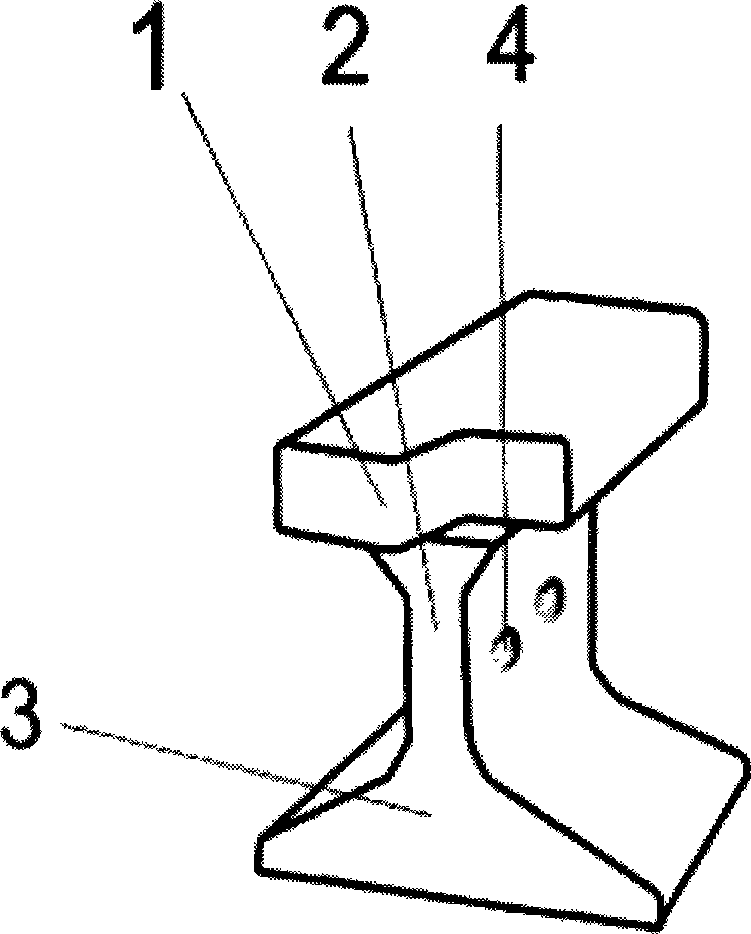
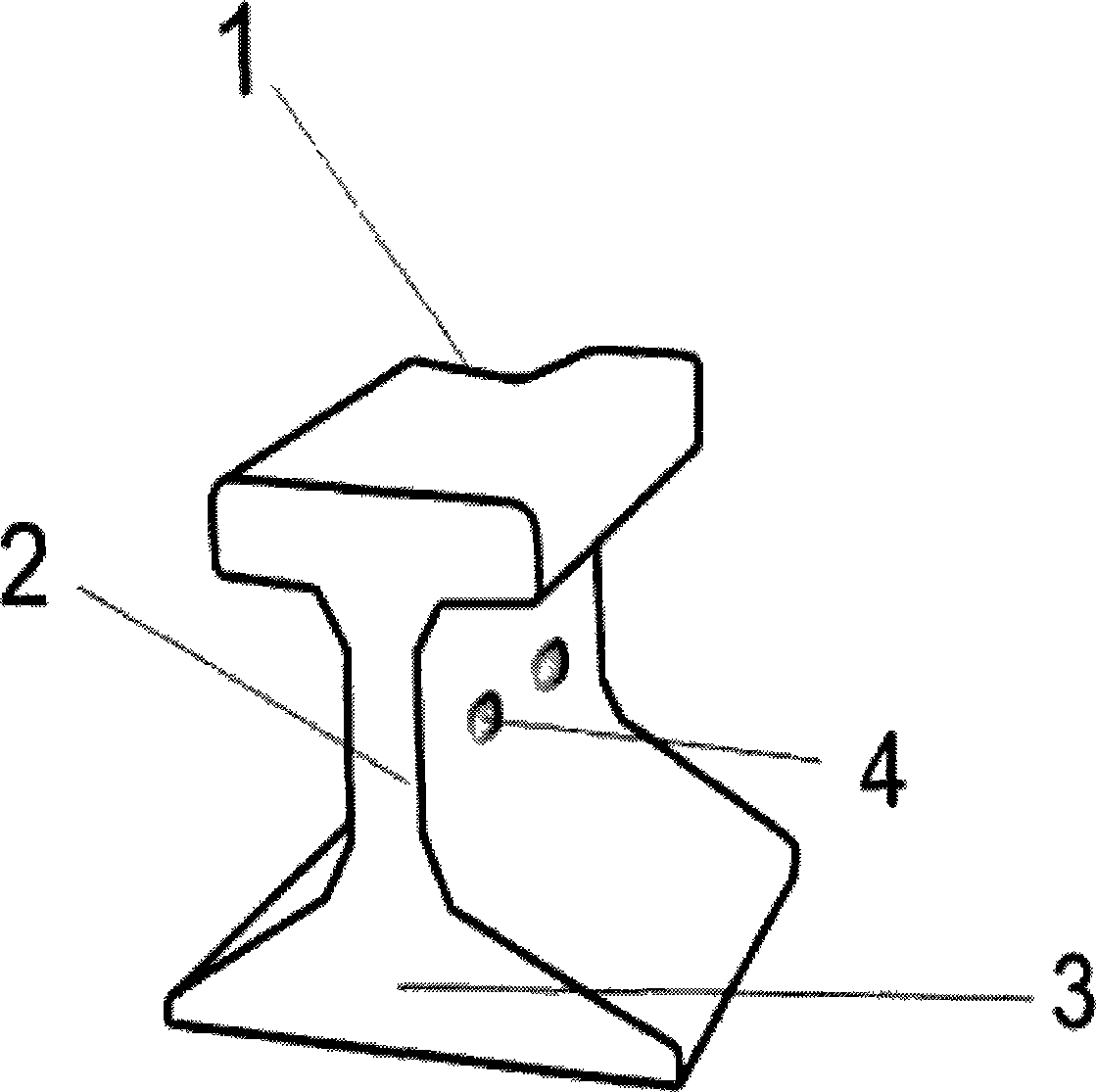
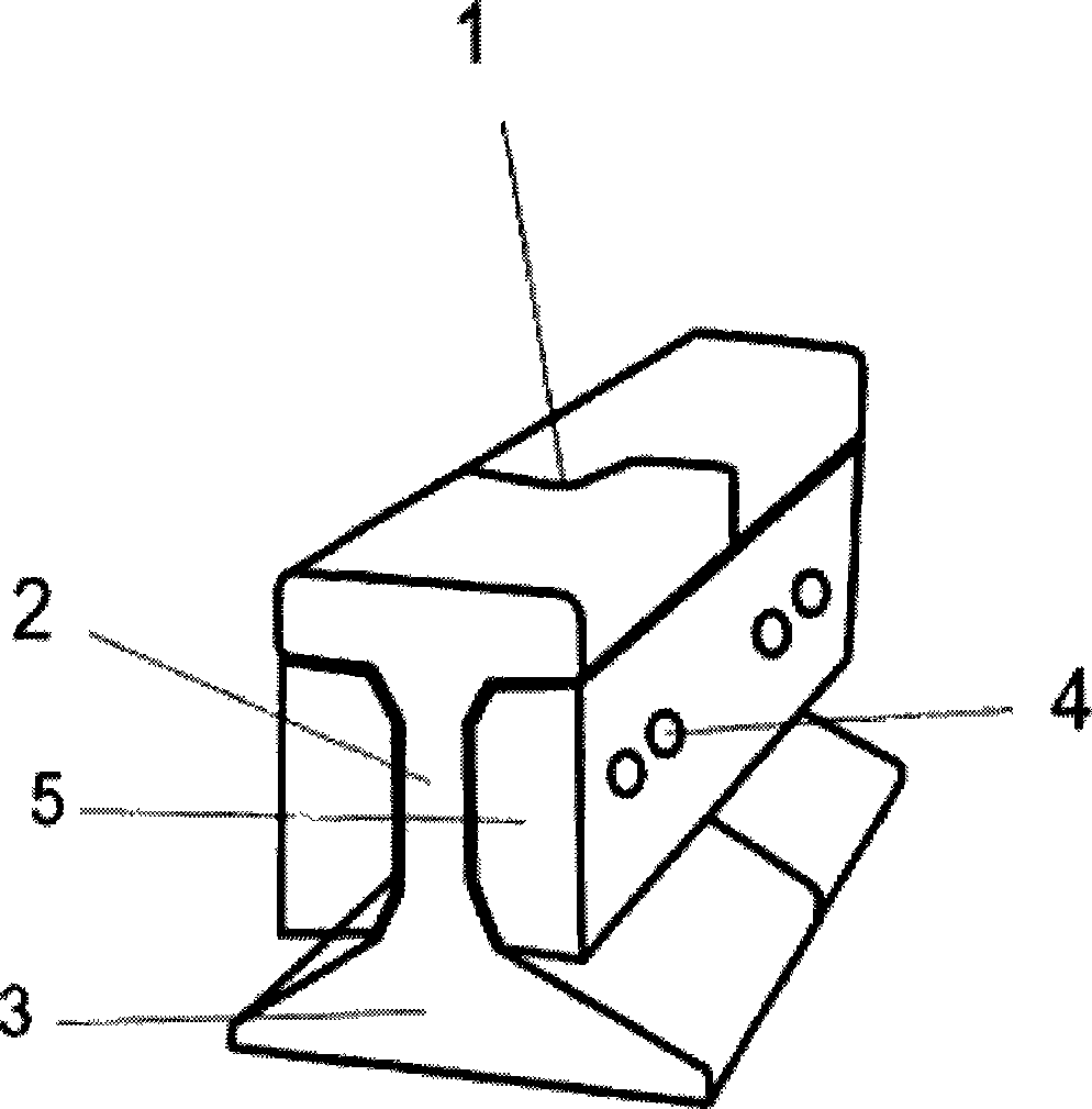
[0014] A new type of railway rail joint, which changes the part of the rail head (1) where the "I"-shaped rail contacts the wheel from a flat surface to two "mortise" shaped joints with half protruding and half recessed, that is, " "The shape of the middle rail waist (2) and the bottom (3) remain unchanged. When laying the rail, align any two joints, put them into the steel plate (5), and fix them with screws (4).
[0015] A new type of railway rail head, which is to change the "I"-shaped rail head (1) in contact with the wheel from a flat surface to a 50° inclined joint. The two ends of the inclined plane are straight lines, and the joint between the straight line and the inclined plane is a straight line. shape, the middle rail waist (2) and the bottom (3) of the rail remain unchanged. For the auxiliary rail, align any two joints, put in the steel plate (5), and fix it with screws (4).

PUM

no PUM

Description & Claims & Application Information

We can also present the details of the Description, Claims and Application information to help users get a comprehensive understanding of the technical details of the patent, such as background art, summary of invention, brief description of drawings, description of embodiments, and other original content. On the other hand, users can also determine the specific scope of protection of the technology through the list of claims; as well as understand the changes in the life cycle of the technology with the presentation of the patent timeline. Login to view more.

Similar technology patents

Air-floated high-speed motorized spindle

InactiveCN102489726AEliminate mechanical frictionReduce frictionMachine tool componentsLarge fixed membersStatorEngineering
Owner:GUANGZHOU HAOZHI ELECTROMECHANICAL

Classification and recommendation of technical efficacy words

  • Increase driving speed
  • Reduce friction

Friction reducing composition and method

Owner:LUBRIZOL OILFIELD SOLUTIONS

Carrier with integrated ducting

ActiveUS20120110909A1Reduce frictionLimiting bindingAir-treating devicesVehicle sub-unit featuresAirflowWindow shutter
Owner:MAGNA INTERNATIONAL INC
Why Eureka
Try Eureka