Control method for clutch arrangement

A clutch device, calculated technology, applied in clutches, control devices, transportation and packaging, etc., can solve the problems of complex use of proportional valves, and achieve the effects of simple cost, less construction labor, and cost saving

Active Publication Date: 2012-09-05
MAGNA POWERTRAIN AG & CO KG
View PDF0 Cites 0 Cited by
  • Summary
  • Abstract
  • Description
  • Claims
  • Application Information

AI Technical Summary

Problems solved by technology

However, the use of these proportional valves is also undesirably complicated

Method used


Image

  • Control method for clutch arrangement
  • Control method for clutch arrangement
  • Control method for clutch arrangement

Examples


Embodiment Construction

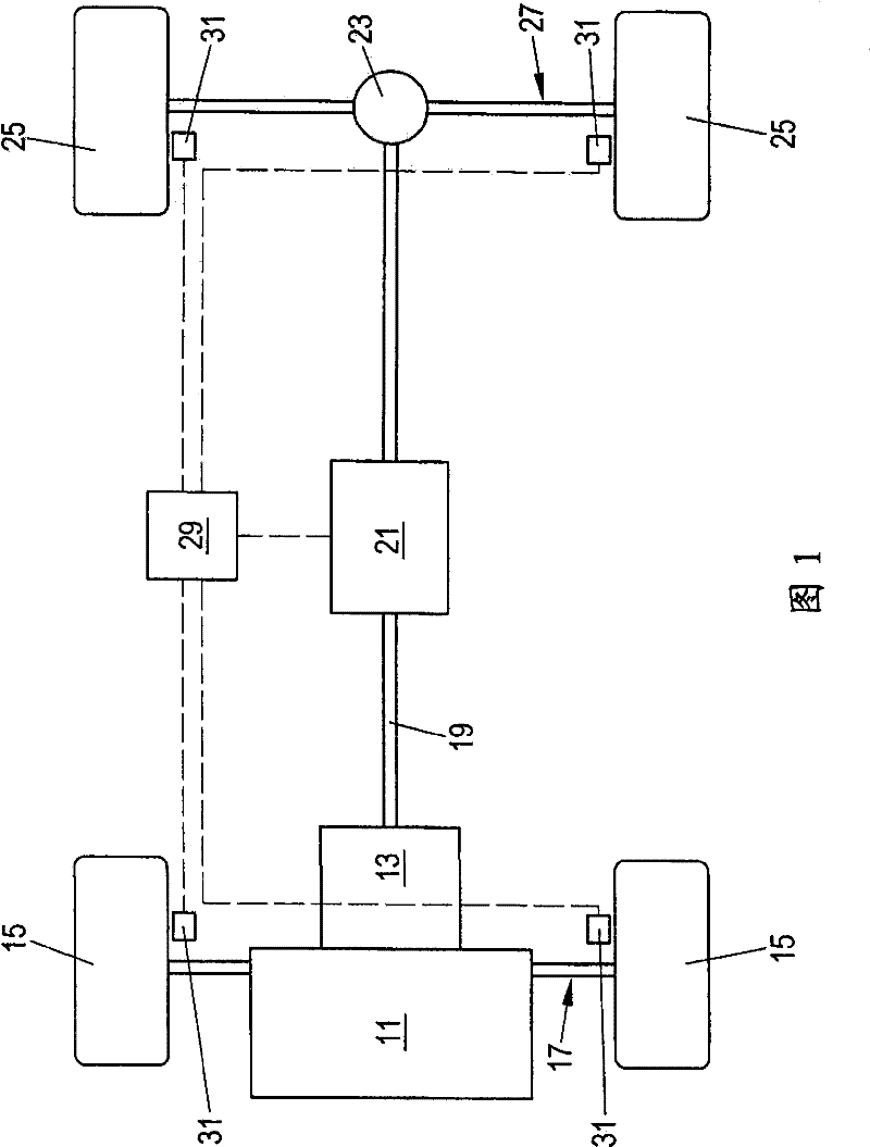
[0046] figure 1 A drive train of a motor vehicle is shown in a schematic representation. The engine 11 drives two wheels 15 of a front axle 17 through a transmission unit 13 and a front axle differential gear (not shown). Thus, the front axle 17 forms the main axle. Furthermore, the engine 11 drives the two wheels 25 of the rear axle 27 via the transmission unit 13 , the cardan shaft 19 , the clutch device 21 and the rear axle differential gear 23 . In this regard, the rear axle 27 forms the secondary axle of the motor vehicle. The electronic control unit 29 of the motor vehicle is connected on the input side to four wheel speed sensors 31 associated with the front wheels 15 and the rear wheels 25 . Alternatively, the control unit 29 may be connected to further sensors, for example to a steering angle sensor, a yaw rate sensor, etc. (not shown). The control unit 29 is connected to the clutch device 21 on the output side. The clutch device 21 is used to transmit some of th...


PUM


Abstract

The invention provides a method controlling a clutch arrangement that serves, in a powertrain of a motor vehicle, for the transmission of a torque from an input element to an output element. Starting from an activated state of the clutch arrangement, a respective estimated torque value is calculated in repeating calculation cycles. A torque build-up value is calculated in dependence on at least one speed difference value. A torque reduction value is calculated in dependence on at least the last calculated estimated torque value. The estimated torque value is re-calculated on the basis of the last calculated estimated torque value by up integration of the calculated torque build-up value and down integration of the calculated torque reduction value. The recalculated estimated torque value is compared with a torque threshold value. The clutch arrangement is deactivated when the recalculated estimated torque value is below the torque threshold value.

Description

technical field [0001] The present invention relates to a method for the control of a clutch device used in a power train of a motor vehicle to transmit torque from an input to an output, in particular the clutch device is responsive to a difference in speed Hydromechanical (hydrodynamic) variable speed clutch device. Background technique [0002] For example, such a clutch arrangement may be used in an all-wheel drive motor vehicle to transfer the drive torque of the drive unit to to the countershaft. In other applications, such a clutch arrangement can be used as a replacement for an axle differential for transmitting drive torque to the half-shaft of an axle acting as a brake for a longitudinal differential of an all-wheel drive motor vehicle (block) or as a braking part of the axle differential. [0003] Such a clutch device has an input part and an output part, such as an input shaft and an output shaft, which are rotatable relative to each other. The clutch arrange...

Claims


Application Information

Patent Timeline
Patent Type & Authority Patents(China)
IPC IPC(8): F16D48/06F16D48/12B60K23/08
CPCF16D48/02B60K23/08F16D48/066F16D2500/1045F16D2500/30401F16D2500/30406F16D2500/30415F16D2500/30426F16D2500/3115F16D2500/70406F16D2500/70605B60K17/02B60K17/34B60K23/04
Inventor 马丁·帕里格尔托马斯·利诺尔特内尔西蒙·凯姆尔黑里贝特·迪特里克
Owner MAGNA POWERTRAIN AG & CO KG
Why Eureka
Try Eureka