Method and circuit arrangement for determining the position of a movable armature of an electromagnetic actuator

A technology of electromagnetic actuators and circuit devices, applied in fluid pressure actuation devices, valve operation/release devices, circuits, etc., to achieve the effects of improving temperature characteristic curves, reducing jitter, and reducing temperature correlation

Active Publication Date: 2022-05-17
ROBERT BOSCH GMBH
View PDF5 Cites 0 Cited by
  • Summary
  • Abstract
  • Description
  • Claims
  • Application Information

AI Technical Summary

Problems solved by technology

Both amplifier types have inherently noisy

Method used


Image

  • Method and circuit arrangement for determining the position of a movable armature of an electromagnetic actuator
  • Method and circuit arrangement for determining the position of a movable armature of an electromagnetic actuator
  • Method and circuit arrangement for determining the position of a movable armature of an electromagnetic actuator

Examples


Embodiment Construction

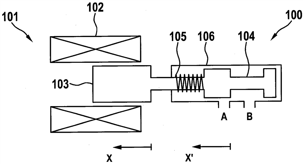
[0031] exist figure 1 A solenoid valve 101 is schematically shown in FIG. 1 , in which the method according to the invention can be carried out. Solenoid valve 101 , which is presently designed as a proportional valve, has a solenoid actuator 101 , which in turn has a coil 102 and an armature 103 movable in this coil.

[0032] Connected to the armature 103 is a control slide valve 104 which can be moved back and forth in a valve housing 106 . The control spool 104 is supported at the end of the valve housing 106 by means of a spring 105 . The armature 103 is moved by controlling the electromagnetic actuator 101 and thus the spool 104 presses against the spring 105 . In this way, the position x of the armature 103 or of the slide valve 104 can be changed. For this purpose, the coil 102 can be controlled, for example (via terminals not shown here) by pulse width modulation.

[0033] Flow from port A to port B through valve housing 106 is regulated by movement of spool valve ...


PUM


Abstract

The invention relates to a method for determining the position of a movable armature (103) of an electromagnetic actuator (101), wherein said armature is movable by means of energization of a coil (102) of the electromagnetic actuator (101), wherein a semiconductor switch (M1), a current measuring resistor circuit (RS) and said coil (102) are connected in series, wherein said armature (103) is positioned (x) in consideration of an oscillating signal in an oscillating electrical system The frequency is determined in the case where the coil (102) is used as a frequency-affecting element of an oscillating electrical system, where the circuit point between the coil (102) and the current measuring resistor circuit (RS) The potential at is adjusted to the desired value by means of the semiconductor switch (M1).

Description

technical field [0001] The invention relates to a method and a circuit arrangement for determining the position of an armature of an electromagnetic actuator which can be moved by controlling a coil of the electromagnetic actuator. Background technique [0002] Electromagnetic actuators are known which have an armature and a coil, wherein the armature can be moved by energizing the coil. Such solenoid actuators are often used in solenoid valves, for example for hydraulic applications. In this case, such a solenoid valve can be used as a proportional valve by, for example, controlling the coil in a pulse-width modulated manner. Here, an average current occurs in the coil due to the inductance. As a counter force to the magnetic force, a spring can be provided here, however, for example, other coils are also conceivable. [0003] However, the actual position of the armature and thus, for example, of the control slide connected to the armature often does not correspond to th...

Claims


Application Information

Patent Timeline
Patent Type & Authority Patents(China)
IPC IPC(8): H01F7/16H01F7/18F16K31/06
CPCF16K31/0668F16K31/0675H01F7/1607H01F7/1844H01F2007/185F16K37/0041H01F7/16H01F7/18F15B13/0442F15B2013/0409
Inventor T.基尔希纳
Owner ROBERT BOSCH GMBH
Why Eureka
Try Eureka