Actuators for hydraulic valve and thehydraulic valve

一种致动器、液压阀的技术,应用在液压的换向阀或压力调节阀,液压阀领域,能够解决影响动态、影响液压阀运行等问题,达到摩擦减小、高稳定性的效果

Active Publication Date: 2021-02-05
ECO HLDG 1 GMBH
View PDF8 Cites 0 Cited by
  • Summary
  • Abstract
  • Description
  • Claims
  • Application Information

AI Technical Summary

Problems solved by technology

Furthermore, an undesirably high damping should not occur, since this influences the dynamics and thus the operation of the hydraulic valves

Method used


Image

  • Actuators for hydraulic valve and thehydraulic valve
  • Actuators for hydraulic valve and thehydraulic valve
  • Actuators for hydraulic valve and thehydraulic valve

Examples


Embodiment Construction

[0031] In the figures, the same or the same type of parts are denoted by the same reference numerals. The drawings show examples only and are not to be construed as limiting.

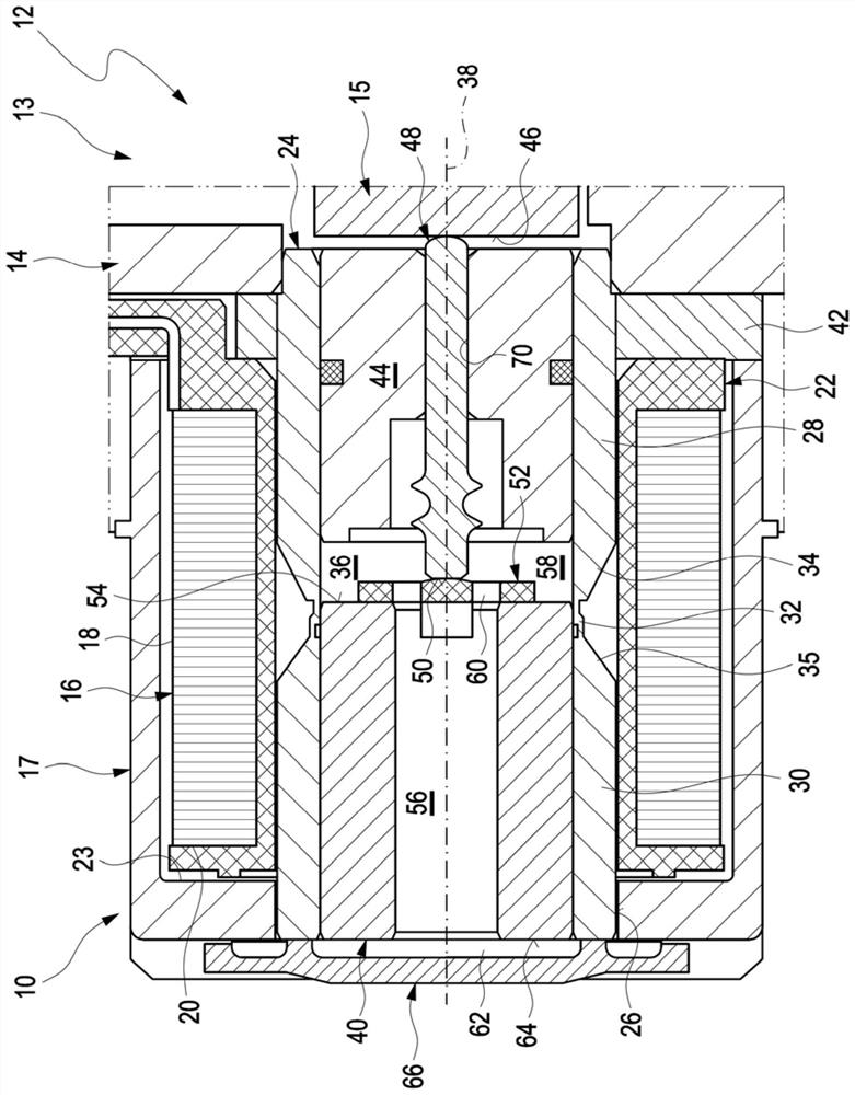
[0032] An actuator 10 of a hydraulic valve 12 according to the prior art is shown in longitudinal section in FIG. 1 . Proceeding from the actuator 10, the hydraulic valve 12, shown simplified among its components configured for hydraulic functions, also comprises a control valve 13, which has a housing 14 with hydraulic connections, which There is an axially movable hydraulically permeable piston 15 , which is accommodated axially displaceably in order to release and close a throughflow opening formed in the housing 14 . The piston 15 is positioned axially by means of the actuator 10 .

[0033] The actuator 10 comprises a magnetizable actuator housing 17 which surrounds the solenoid coil 16 on its outer circumference 18 and on at least one end face 20 of the solenoid coil. For reasons of electrical ins...


PUM


Abstract

The invention relates to an actuator for a hydraulic valve, in particular for a hydraulic reversing valve or a pressure control valve of a motor vehicle, the actuator including a magnetisable actuatorhousing that envelops a magnet coil; a pole group arranged in a receiving opening of the actuator housing, wherein the pole group includes a pole core and a pole tube, wherein an axially movable armature is arranged in an inner cavity of the pole group, wherein the armature is configured to axially move a piston of the hydraulic valve by a pin that is supported axially movable in the pole group,wherein the actuator is configured to perform an anti-stick function and a contact damping function, wherein the pin directly contacts a first armature face of the armature that is oriented towards the pin, and wherein the pin is configured axially movable relative to the armature. The invention further relates to a hydraulic valve.

Description

technical field [0001] The invention relates to an actuator for a hydraulic valve, and a hydraulic valve, in particular a hydraulic directional valve or pressure regulating valve for a motor vehicle. Background technique [0002] It is known to use electromagnetic actuators for the axial movement of pistons, for example of hydraulic directional valves or pressure regulating valves, ie hydraulic valves. The actuator has an armature which is accommodated in a substantially hollow-cylindrical configuration so that it can move axially. Thus, the armature can move axially in the cylindrical space enclosed by the pole group, which space is filled with hydraulic fluid. This space is essentially closed, ie hydraulic fluid has to flow from one side of the armature to the other side of the armature during the movement of the armature, which leads to a pressure loss. This produces on the armature a force directed against the movement of the armature, which is speed-dependent and is r...

Claims


Application Information

Patent Timeline
Patent Type & Authority Applications(China)
IPC IPC(8): F16K31/06F15B13/02
CPCF16K31/0675F15B13/02F16K31/0686H01F2007/1661H01F7/088H01F7/1607F16K31/0644
Inventor 托马斯·杰克布约翰纳斯·克雷博斯戴安娜·诺伊费尔德
Owner ECO HLDG 1 GMBH
Why Eureka
Try Eureka