Supercharge Your Innovation With Domain-Expert AI Agents!

Flowmeter

A flowmeter, electromagnetic flowmeter technology, applied in the application of electromagnetic flowmeter to detect fluid flow, liquid/fluid solid measurement, test/calibration volume flow, etc., can solve problems such as flow measurement system errors

Active Publication Date: 2009-03-18
ABB AS
View PDF0 Cites 7 Cited by
  • Summary
  • Abstract
  • Description
  • Claims
  • Application Information

AI Technical Summary

Problems solved by technology

However, the operating temperature of the flowmeter may differ significantly from room temperature, so the flow measurements obtained will exhibit systematic errors due to miscalibration
Aging of components will also introduce additional errors in flow measurements

Method used


Image

  • Flowmeter
  • Flowmeter
  • Flowmeter

Examples


Embodiment Construction

[0020] overview

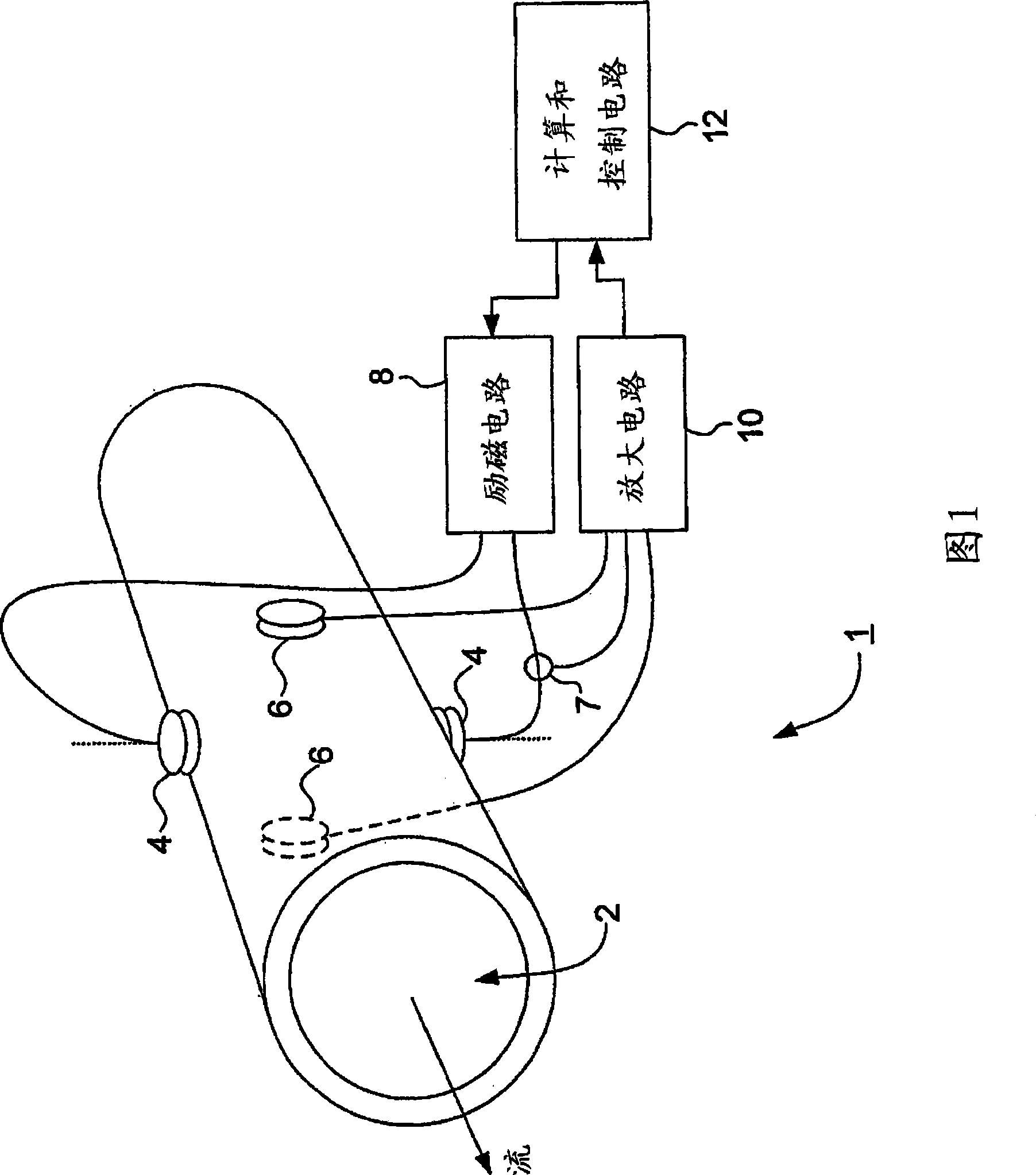
[0021] Figure 1 shows a flowmeter 1 having: a conduit 2 along which the fluid to be measured can flow; a pair of field coils 4 located at diametrically opposite points along the conduit 2 perpendicular to the direction of flow; and a pair of electrodes 6, It is perpendicular to the flow direction and is also arranged perpendicular to the field coil 4 . The excitation coil 4 is connected to an excitation circuit 8 , and the electrode 6 is connected to an amplification circuit 10 . A current sensor 7 is also provided to sense the current applied to the exciting coil 4 , and the output of the current sensor 7 is also connected to the amplification circuit 10 . Both the exciting circuit 8 and the amplifying circuit 10 are connected to a calculation and control circuit 12 which controls the driving of the exciting circuit 8 and processes a signal obtained from the amplifying circuit 10 .

[0022] In operation, the calculation and control circuit 12 sets the pa...


PUM


Abstract

An electromagnetic flowmeter assembly is described in which an excitation field is set up across a flow conduit and electrodes are used to sense the electromagnetic field generated across the flow conduit as a result of interaction between the excitation field and fluid flowing along the flow conduit. The signals obtained from the electrodes are processed, together with stored calibration data, by processing circuitry to determine flow measurements and means is provided for dynamically updating the calibration data.

Description

technical field [0001] The invention relates to a flow meter and its components, in particular to an electromagnetic flow meter with self-calibration function. Background technique [0002] Previously, flowmeters were factory pre-calibrated, ie, at the time of production, each component of the flowmeter system including the field coil, amplifier circuit, and control circuit was calibrated individually and assembled together to form the flowmeter system. Calibration of amplifier and control circuits is usually performed at room temperature. However, the operating temperature of the flowmeter may differ significantly from room temperature, and therefore, the flow measurements obtained will exhibit systematic errors due to miscalibration. Aging of components will also introduce additional errors in flow measurements. Contents of the invention [0003] It is therefore an object of the present invention to solve this problem by providing a flow meter with a self-calibration f...

Claims


Application Information

Patent Timeline
Patent Type & Authority Applications(China)
IPC IPC(8): G01F1/58G01F1/60G01F25/00
CPCG01F1/588G01F25/0007G01F1/60G01F25/10G01F1/58
Inventor 特罗伊·雷
Owner ABB AS
Features
  • R&D
  • Intellectual Property
  • Life Sciences
  • Materials
  • Tech Scout
  • Unparalleled Data Quality
  • Higher Quality Content
  • 60% Fewer Hallucinations
Learn More