
Intraocular drug dispenser

A drug dispenser, eyeball technology, applied in the direction of drug delivery, drug combination, medical formula, etc., can solve the problems of healthy eye damage, eye infection, etc.

Inactive Publication Date: 2009-03-18
NULENS
View PDF5 Cites 3 Cited by
  • Summary
  • Abstract
  • Description
  • Claims
  • Application Information

AI Technical Summary

Problems solved by technology

Injection of this specific amount of drug is currently performed by eye syringes, although such eye syringes can cause damage to even healthy eyes and can lead to eye infections and other undesirable conditions

Method used


Image

  • Intraocular drug dispenser
  • Intraocular drug dispenser
  • Intraocular drug dispenser

Examples


Embodiment Construction

[0010] Specific implementation examples

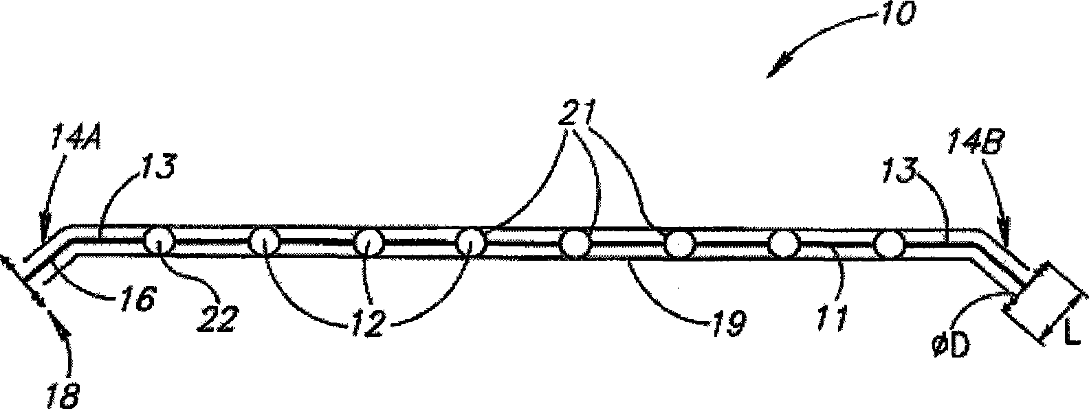
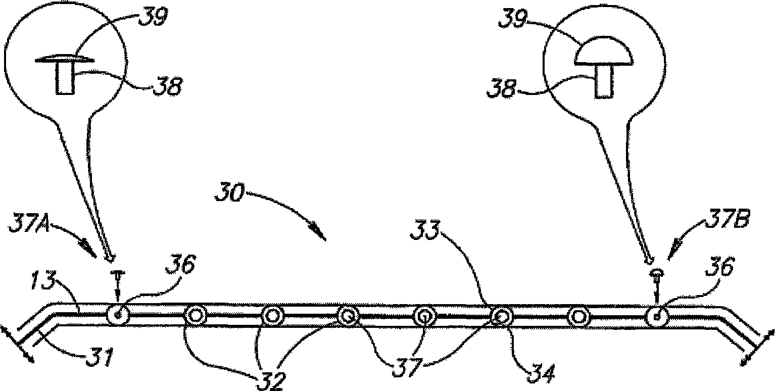
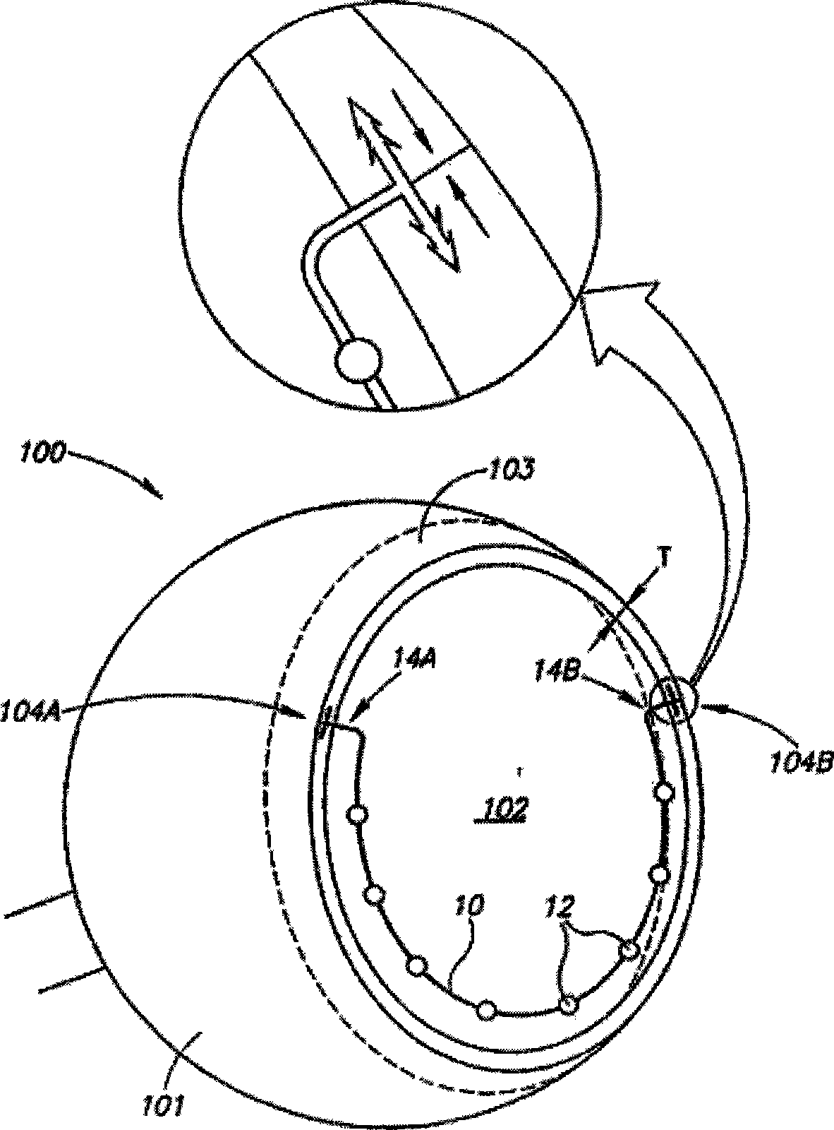
[0011] figure 1 An intraocular medicament dispenser 10 is shown comprising an elongated support member 11 having a series of spaced apart medicated capsules 12 and a pair of opposing ends 13 . The T-shaped structural members 14A and 14B are mounted on opposite ends 13 so that the intraocular drug dispenser 10 can be securely mounted on the eye. The T-shaped fixing elements 14A and 14B are bent at an obtuse angle α≈170° with the support member 11, which can assist in implanting the intraocular drug dispenser 10 in the eye. Each T-shaped fixation element 14 includes a strut 16 and a pair of opposing elongated anchor-shaped fixation elements 17 that directly self-fixate. The anchor-shaped fixing element 17 is provided with an end structure 18, which may be a structure of barb hairs, barbs, etc., so as to be fixed to the wall of the eye. The drug-containing capsule 12 is wrapped by a soft silicone sheath 19 to protect the delicate struc...


PUM


Abstract

Intraocular drug dispenser includes an elongated support member with a pair of opposite ends for anchoring to opposite surfaces of an eye's eye wall, and a string of discrete drug containing capsules for individual time controlled release of their drug contents into an eye's vitreous cavity.

Description

technical field [0001] The present invention relates to intraocular drug dispensers. Background technique [0002] A typical intraocular drug dispenser includes a drug chamber from which the drug can be released by diffusion or osmosis through a membrane, so that the drug can be continuously delivered to the vitreous cavity of the eye over a relatively long period of time. However, when using this intraocular drug dispenser to dispense drugs, it is often hindered by the natural fibrous tissue growing on it, causing the actual drug distribution rate to be lower than the expected rate, resulting in damage to the expected therapeutic effect. [0003] Several other slow intraocular drug release devices are illustrated and described in US patents. Such as, inter alia, US Patent 5,098,443 to Parel et al., US Patent 5,466,233 to Weiner et al., US Patent 5,830,173 to Avery et al., and US Patent Application Publication No. 2002 / 0110591 to Brabaker et al. These are generally specifi...

Claims


Application Information

Patent Timeline
Patent Type & Authority Applications(China)
IPC IPC(8): A61F9/00
CPCA61K9/0009A61F9/0017A61K9/0051A61P27/02
Inventor 约书亚·本纳
Owner NULENS
Learn More