Spiral type gas-solid separation device

A gas-solid separation, spiral technology, applied in separation methods, dispersed particle separation, chemical instruments and methods, etc., can solve the problems of high flight direction requirements, limited gas-solid separation efficiency, large airflow pressure loss, etc. Complete solid separation, low cost and small pressure loss

Inactive Publication Date: 2010-07-14
GUANGZHOU UNIVERSITY
View PDF1 Cites 1 Cited by
  • Summary
  • Abstract
  • Description
  • Claims
  • Application Information

AI Technical Summary

Problems solved by technology

Although the spiral centrifugal dust collector overcomes the interference problem of the airflow, it has some disadvantages: (1) the airflow moves downward, and the pressure loss of the airflow is relatively large; Flying out of the small holes requires high requirements for the flying direction of the particles, so that some particles remain on the wall of the centrifuge tube and cannot be taken out of the centrifuge tube, but still move with the airflow, and the efficiency of gas-solid separation is limited; (3) The wall of the centrifuge tube has a small The hole also allows part of the airflow to enter the dust container, thereby stirring the dust in the dust container to fly, and some dust will return to the centrifuge chamber through the small hole, and back-mixing occurs; (4) The wall of the centrifuge needs to be opened, which is not convenient Add spray and other strengthening measures to improve the gas-solid separation effect

Method used


Image

  • Spiral type gas-solid separation device
  • Spiral type gas-solid separation device
  • Spiral type gas-solid separation device

Examples


Embodiment Construction

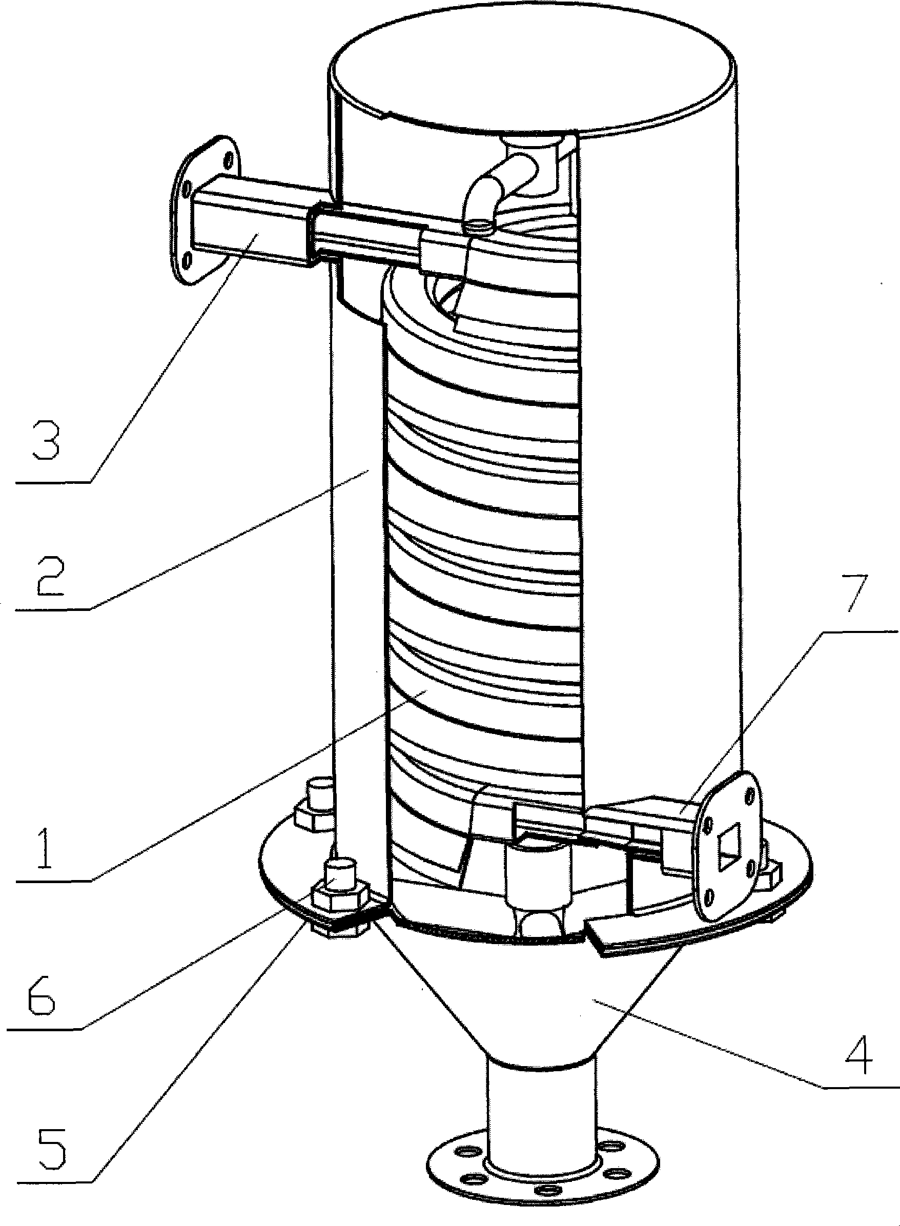
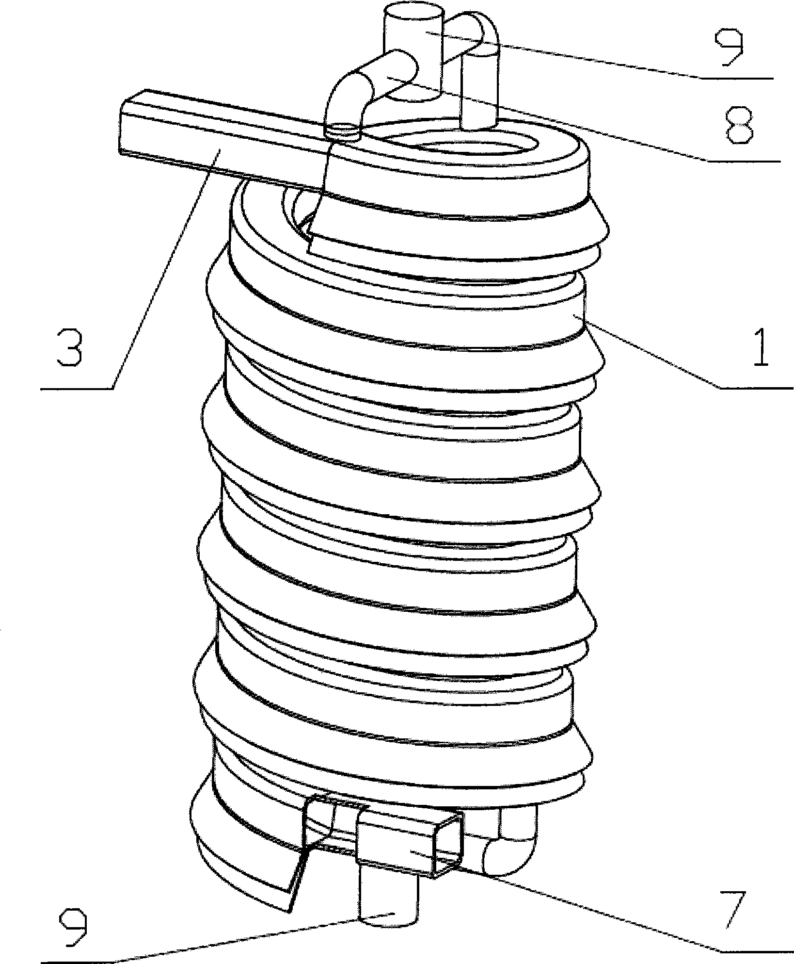
[0020] like figure 1 As shown, the bell mouth of the conical dust collector 4 is connected with the cylindrical sealing cover 2 by the bolt 6, and the spiral air flow channel 1 is coaxially arranged in the cover, and the air flow inlet 7 and the outlet 3 of the channel are connected by the cylindrical sealing cover 2 respectively. The lower and upper side walls protrude. The bolts 6 pass through the bell mouth of the conical dust collector 4 and the flanges 5 at the bottom of the cylindrical sealing cover 2 respectively, and a gasket is arranged between the two flanges 5 . The intersection of the outer wall 1-3 of the spiral air flow passage 1 and the lower wall 1-4 is provided with a slit 1-5, and the outer wall 1-3 and the lower wall 1-4 of the spiral air flow passage 1 on both sides of the slit 1-5 respectively face The oblique downward extension of the side wall of the cylindrical sealing cover 2 forms an upper skirt 1-1 and a lower skirt 1-2 (see image 3 ).

[0021] l...


PUM


Abstract

The invention discloses a spiral gas-solid separation device, which comprises a conical dust collector (4), and is characterized in that a cylindrical seal cover (2) is arranged on a horn mouth of the conical dust collector (4), a spiral air current channel (1) is disposed in the cover coaxially, and an air current inlet (7) and an air current outlet (3) of the channel respectively extend out from side walls of the lower part and the upper part of the cylindrical seal cover (2); and a gap (1-5) is arranged at the junction of the outer wall (1-3) and the lower wall (1-4) of the spiral air current channel (1) for dust settling after centrifugal separation. The device has the advantages of rather complete gas-solid separation, non interference of air current flow up and down and low pressureloss.

Description

technical field [0001] The present invention relates to a device using free swirling flow, in particular to a device for separating and discharging solid components in exhaust gas by using inertial or centrifugal separators. Background technique [0002] Since the dust in the air is the enemy that affects human health, people use various dust removal equipment to remove the dust in the air to eliminate the impact of dust on the environment and human health. There are many types of dust collectors, including mechanical dust collectors, filter dust collectors, electric dust collectors, and wet dust collectors. Among them, mechanical dust collectors are gas-solid separation equipment that were used earlier and are easy to operate. [0003] Most of the existing mechanical dust collectors are cyclone dust collectors. Since the appearance of cyclone dust collectors, they have been widely used in industrial dust removal due to their advantages of being able to capture small dust pa...

Claims


Application Information

Patent Timeline
Patent Type & Authority Patents(China)
IPC IPC(8): B01D45/16
Inventor 江帆
Owner GUANGZHOU UNIVERSITY
Why Eureka
Try Eureka