Cam link paper stopping mechanism

A cam link and cam technology, applied in the direction of object separation, pile separation, thin material processing, etc., can solve the problems of unfavorable product production, increase the difficulty and time of assembly, reduce business efficiency, etc., to reduce the cost of components, The effect of improving the profitability of the enterprise and simplifying the assembly process

Inactive Publication Date: 2009-03-25
CAL COMP ELECTRONICS
View PDF0 Cites 5 Cited by
  • Summary
  • Abstract
  • Description
  • Claims
  • Application Information

AI Technical Summary

Problems solved by technology

[0008] The paper feeding roller and the baffle are respectively located at the opposite positions on the upper and lower sides of the body. Because the relative distance between the two is relatively far, it needs to pass through more transmission components to achieve the desired transmission effect, and using a large number of transmission components will It is directly reflected in the cost, and increases the difficulty and time of assembly, consumes a lot of man-hours, is not conducive to product production, and affects the profit of the enterprise
[0009]

Method used


Image

  • Cam link paper stopping mechanism
  • Cam link paper stopping mechanism
  • Cam link paper stopping mechanism

Examples


Embodiment Construction

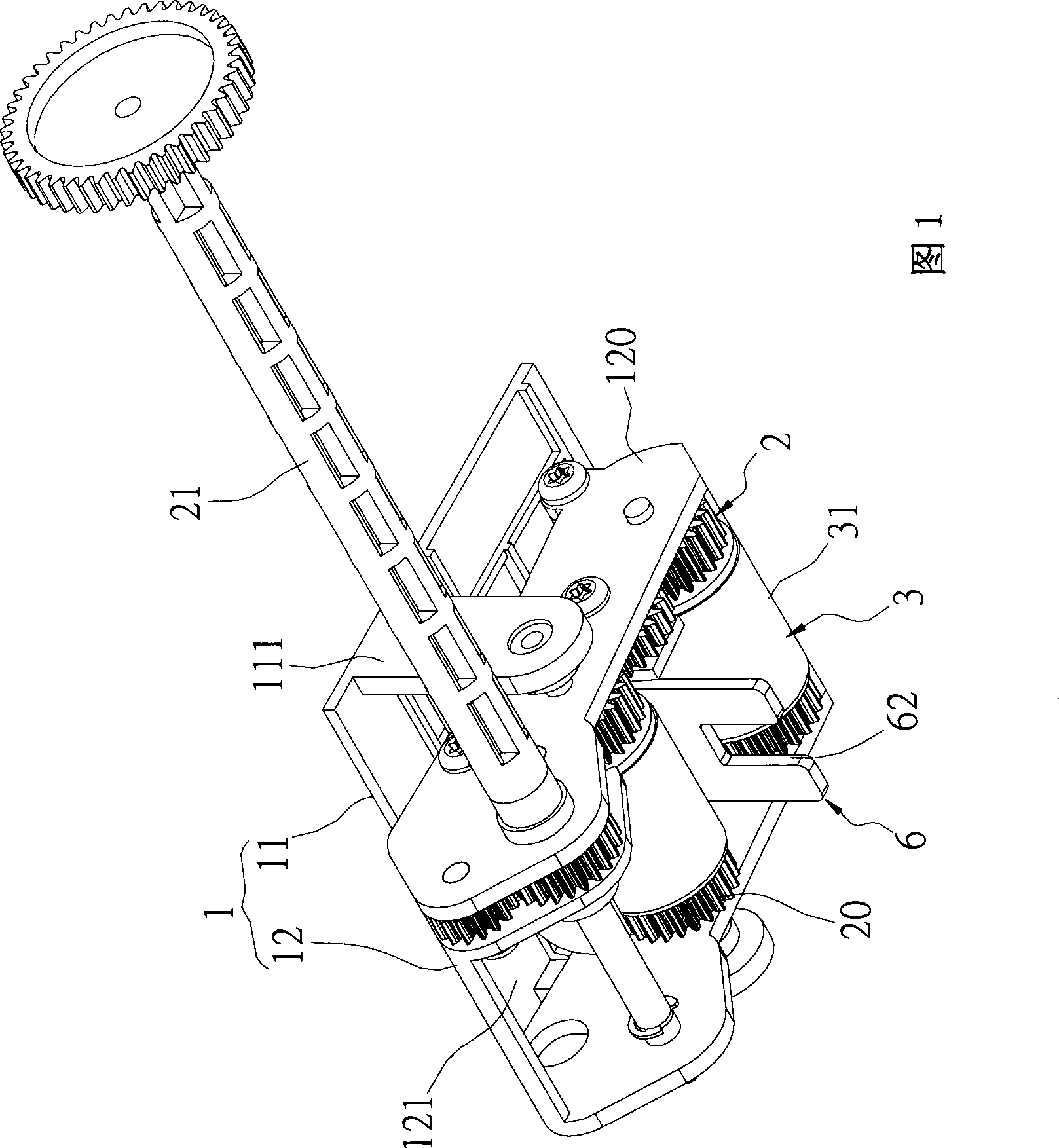
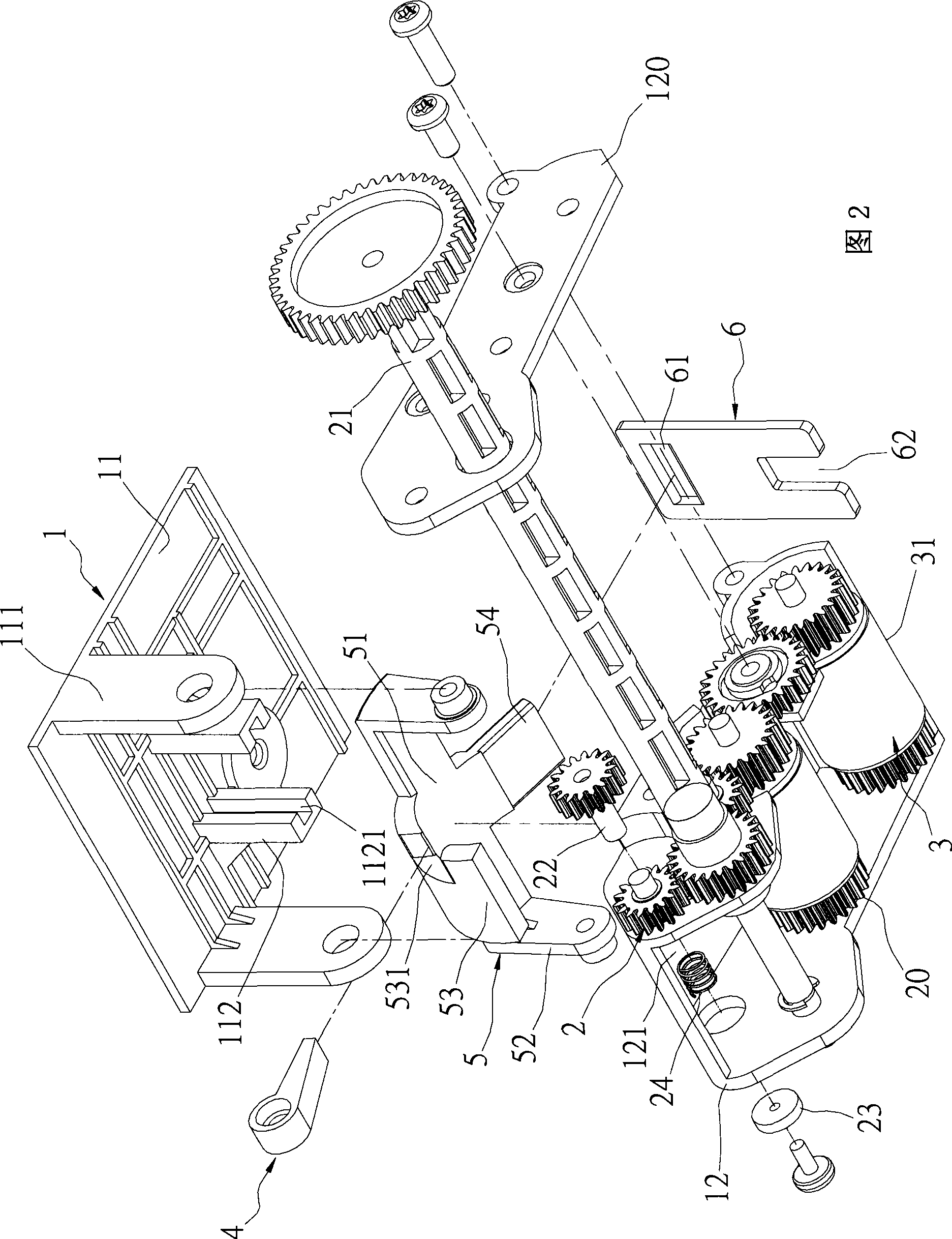
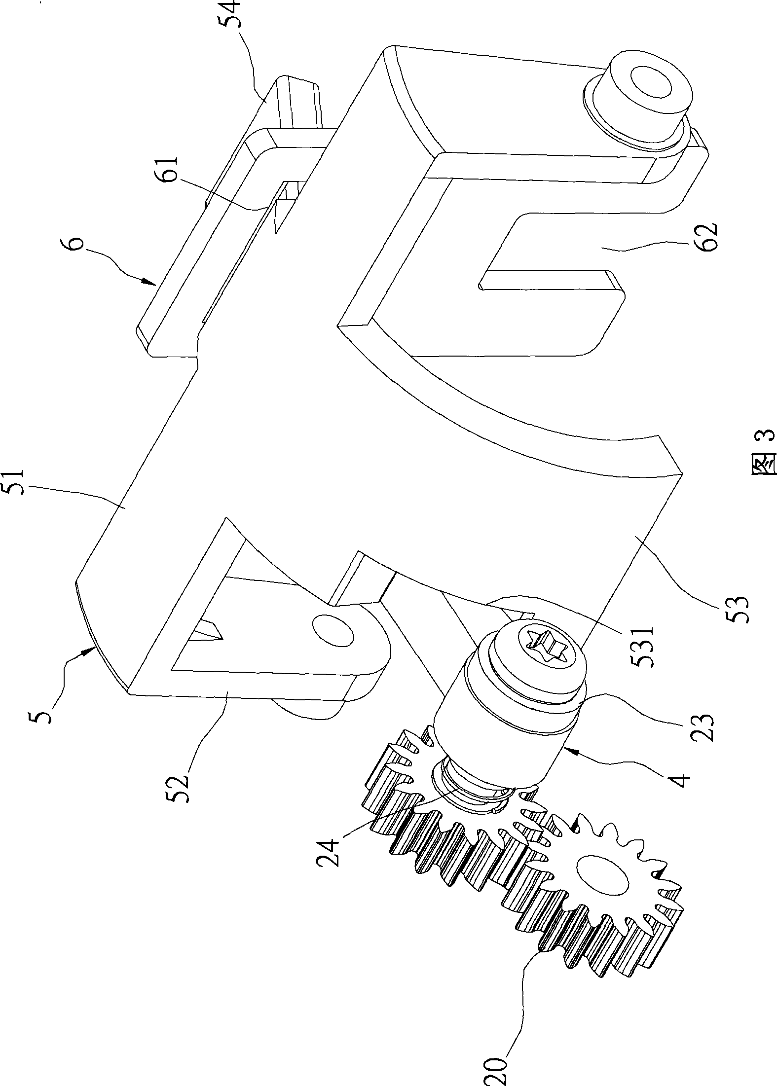
[0053] Please refer to Fig. 1 to Fig. 6, which is the cam-link paper blocking mechanism of the present invention, which is arranged on the body 7 of the business machine, and is necessary for printing operations by various transmission mechanisms, electronic components, and others. As an assembly composed of components, the machine body 7 has a paper placement area 71 for supporting stacks of paper 8 for use when the business machine intends to perform printing operations. The cam-link paper blocking mechanism includes a housing set 1 , a transmission gear set 2 , two paper feeding rollers 3 , a cam 4 , a rotating part 5 and a baffle plate 6 .

[0054] Please refer to FIG. 1 and FIG. 2, the housing set 1 is molded with plastic material, and it includes an upper housing 11 and a lower housing 12, and the upper housing 11 is fixed on the paper placement area 71 of the machine body 7. At the top (as shown in FIG. 4 ), the upper housing 11 has a pair of pivot plates 111 and a pair...


PUM


Abstract

The invention discloses a cam linkage-rod paper-blocking mechanism which comprises a casing unit, a transmission gear unit, two paper-charging rollers, a cam, a blocking plate and a revolving element. The casing unit comprises an upper casing and a lower casing. The upper casing is fixedly arranged on a machine body and the lower casing is arranged below the upper casing in a swinging manner. The lower casing is provided with a containing space and the transmission gear unit is arranged on the lower casing. The paper-charging rollers are arranged in the containing space and are connected with the transmission gear unit. One end of the cam is articulated with the transmission gear unit and the blocking plate is arranged on the upper casing in an up-and-down sliding manner and extends out from the lower casing. The revolving element is articulated with the upper casing and one end of the revolving element is connected with the blocking plate while the other end is connected with the cam. Therefore, the transmission distance between the paper-charging roller and the blocking plate can be shortened and then the expected transmission effect can be realized with less transmission components so as to effectively reduce cost.

Description

technical field [0001] The invention provides a cam-link paper stop mechanism, especially a cam-link paper stop mechanism applied to a business machine. Background technique [0002] Even in the modern era when the technology of communication-related industries is highly developed, although the concept of paperless operations has become common, the transmission of information still inevitably needs to be expressed through paper. After all, paper still has many irreplaceable advantages, such as Easy to carry and easy to modify and circulate. [0003] Generally speaking, business machines have the function of printing. However, in the trend of multi-function communication products, multi-function business machines with functions of scanning, printing, faxing and copying are derived from this and have been widely used. In various fields of society, such as companies, government agencies, academic institutions and even individuals, multi-functional business machines can meet th...

Claims


Application Information

Patent Timeline
IPC IPC(8): B65H3/06B65H3/46
Inventor 张益玮
Owner CAL COMP ELECTRONICS
Why Eureka
Try Eureka