
Closed loop cycle electric heater with decompression apparatus

A pressure relief device and electric heater technology, applied in the field of electric heaters, can solve problems such as hidden dangers, explosion venting, and long-term aging, and achieve the effects of good reliability, high accuracy of pressure relief, and simple structure

Inactive Publication Date: 2009-03-25
倪小美
View PDF0 Cites 7 Cited by
  • Summary
  • Abstract
  • Description
  • Claims
  • Application Information

AI Technical Summary

Problems solved by technology

[0002] The current closed-loop electric heaters on the market include an electric heating group composed of heat exchange blades. The blades are filled with liquid, and an electric heating tube is installed under the inside of the electric heating group. The surface of the electric heating tube exchanges heat with the liquid, but when When the operating components in the electric heater are damaged or fail, the liquid will absorb heat to achieve phase change gasification, and its gasification will form expansion pressure, which will cause the pressure in the electric heating group to increase sharply and endanger the structure of the exchange system, thus Explosion venting causes dangerous consequences, so people try to install a pressure relief valve in the electric heater, but the existing pressure relief valve has a complex structure, low reliability and accuracy, and has long-term aging problems, so it is not suitable for long-term installation. On electric heaters with sealed circuits, it is also easy to cause customer complaints and recycling, and there is a considerable hidden danger

Method used


Image

  • Closed loop cycle electric heater with decompression apparatus
  • Closed loop cycle electric heater with decompression apparatus

Examples


Embodiment Construction

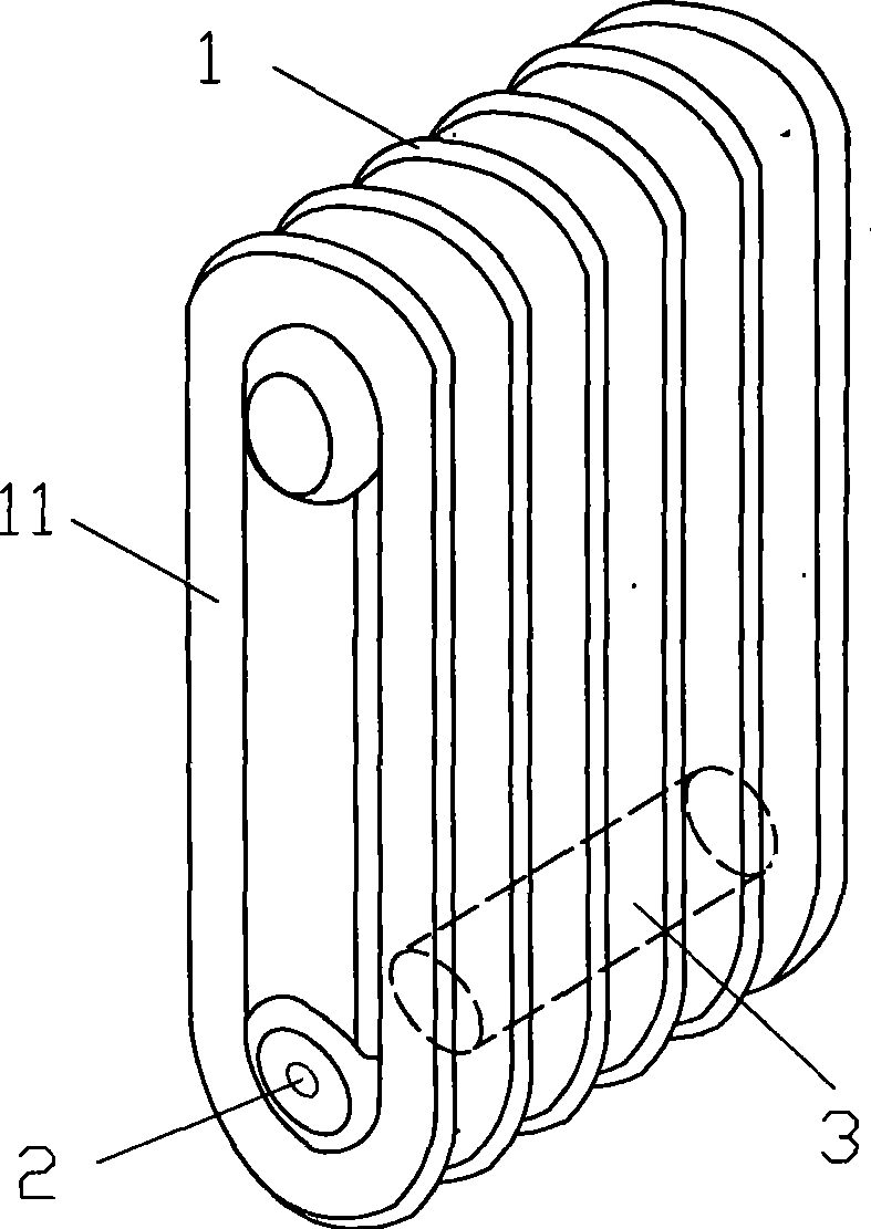
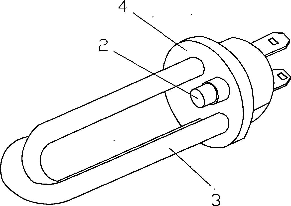
[0013] Refer to figure 1 , figure 2 , A closed-loop circulating electric heater with pressure relief device, comprising an electric heating group 1 composed of heat exchange blades 11, the blades 11 are filled with liquid, and an electric heating tube 3 is arranged below the inside of the electric heating group 1. A pressure relief hole 2 is provided on the heater, and the pressure relief hole 2 is sealed by a low melting point material. The material is a metal alloy with a melting point of 110°C to 180°C. The sealing form can be riveting or welding fusion sealing.

[0014] The pressure relief hole 2 of this product can be arranged at any position of the electric heater, such as: the side wall of the blade 11 or the end seat 4 of the electric heating tube 3 or the electric heating tube 3, in short, as long as it achieves the technology of the present invention by basically the same means The effects should all belong to the protection scope of the present invention.

[0015] The ...


PUM


Abstract

The invention discloses a closed loop circulating electric heater with a pressure release device. The electric heater comprises an electric heating unit consisting of heat exchange blades; the inside of each blade is filled with liquid; the lower part of the inside of the electric heating unit is provided with an electric heating tube; a pressure release hole is arranged on the electric heater and is sealed by a material with a low melting point; when an operating component inside the electric heater is damaged or failed, the liquid can absorb heat, reach phase change and is gasified to form expansion pressure in order that the pressure in the electric heating unit is sharply increased; and when the temperature reaches the set temperature of the melting point of the sealing material, the material with the low melting point begins to melt in order that the overpressure liquid in the electric heating unit can flow out from the pressure release hole, thereby achieving the aim of pressure release. The closed loop circulating electric heater has a simple structure, good reliability, high accuracy of pressure release and no problem of long-term aging, and can be widely applied to the manufacture of the closed loop circulating electric heater.

Description

Technical field [0001] The invention relates to an electric heater, in particular to a closed-loop circulating electric heater. Background technique [0002] The closed loop electric heaters currently on the market include an electric heating group composed of heat exchange blades, the blades are filled with liquid, and an electric heating tube is arranged below the inside of the electric heating group. The surface of the electric heating tube exchanges heat with the liquid, but when When the operating components in the electric heater are damaged or fail, the liquid will absorb heat and reach the phase change gasification, and its gasification will form an expansion pressure, which will cause the pressure in the electric heating group to increase sharply and endanger the structure of the exchange system. Explosion venting will cause dangerous consequences, so people try to install a pressure relief valve in the electric heater. However, the existing pressure relief valve has com...

Claims


Application Information

Patent Timeline
Patent Type & Authority Applications(China)
IPC IPC(8): F24D13/04
Inventor 李喜萍
Owner 倪小美
Learn More