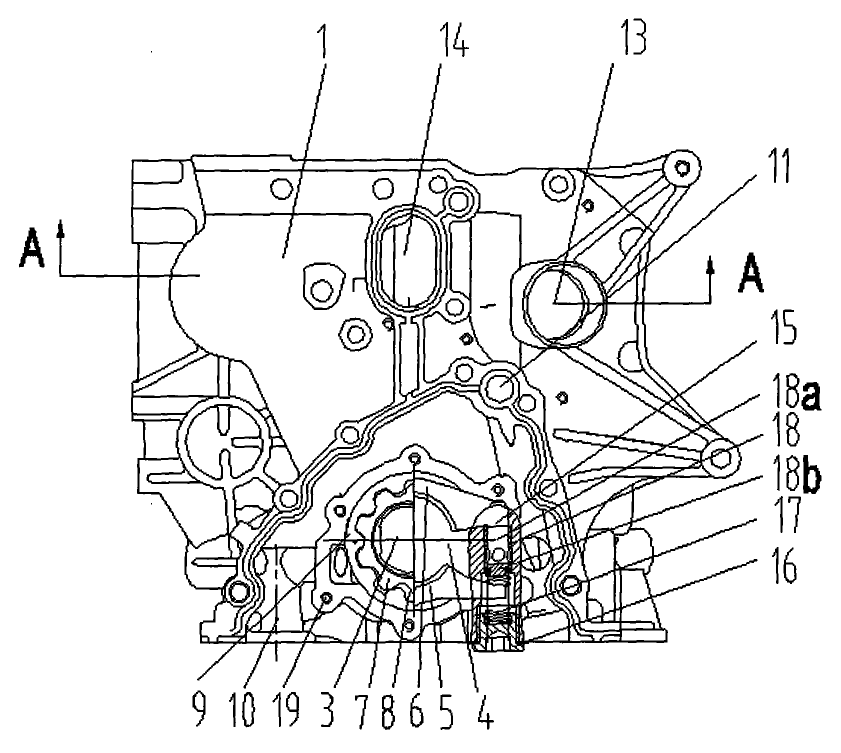
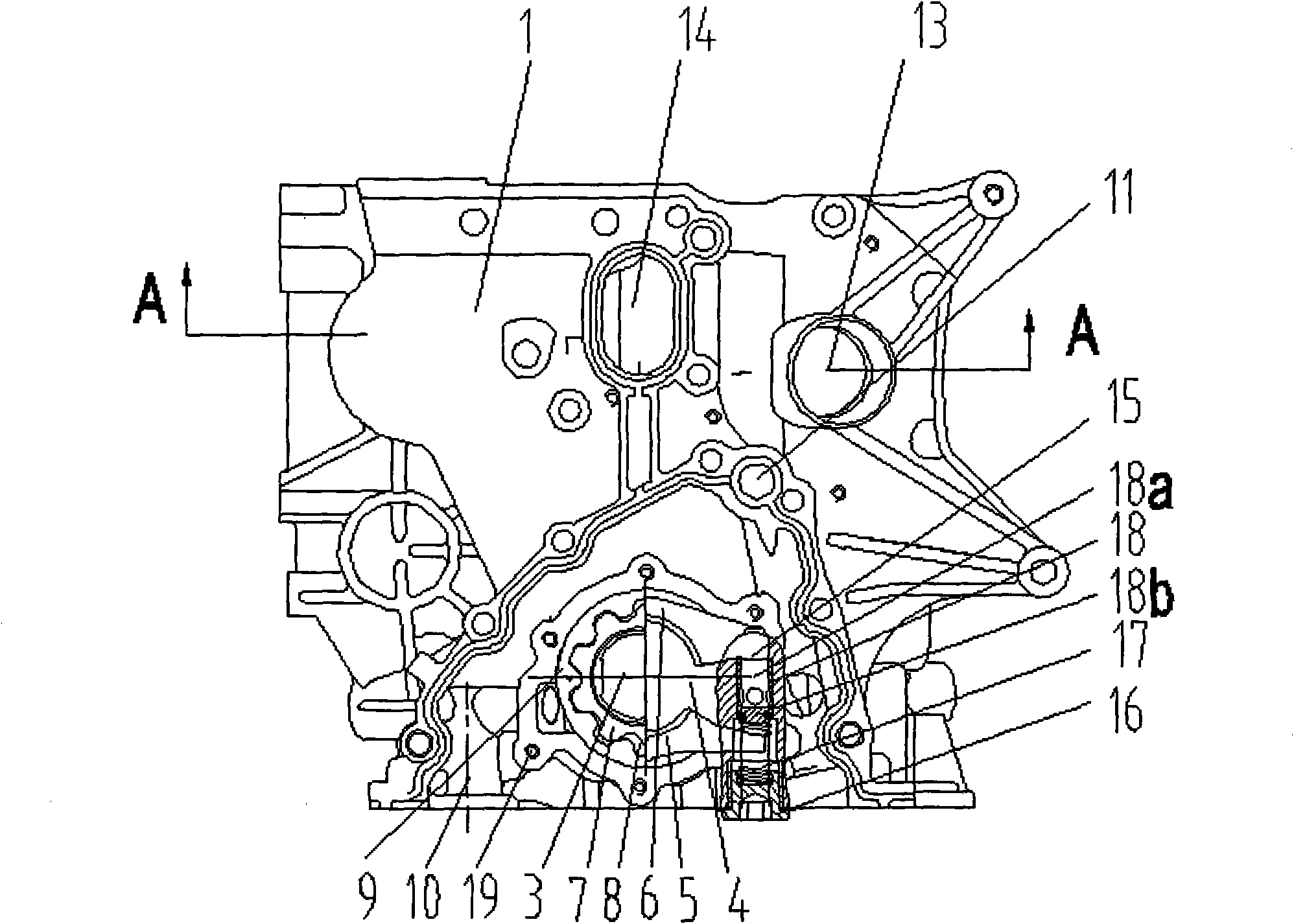
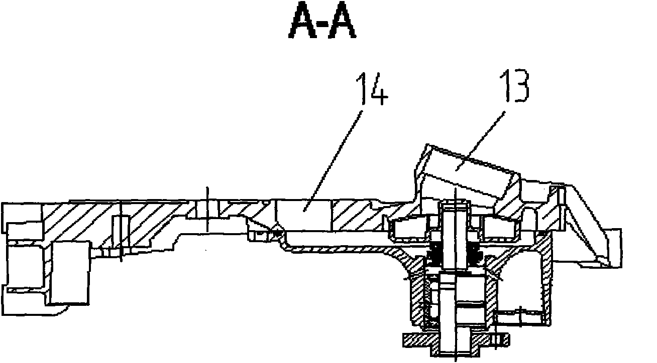
Front end cover assembly for integrated lubrication cooling power pump of engine
A front-end cover and integrated technology, applied in the direction of engine cooling, engine components, machine/engine, etc., can solve the problems of low oil compressibility, non-compactness, and many manufacturing materials, so as to reduce processing difficulty and volumetric efficiency The effect of improving and compact structure
Inactive Publication Date: 2011-01-05
CHONGQING HAITONG INVESTMENT GROUP
View PDF4 Cites 0 Cited by
- Summary
- Abstract
- Description
- Claims
- Application Information
AI Technical Summary
Problems solved by technology
1. The traditional engine lubricating power pump is externally assembled on the front end cover of the engine. This kind of mechanism has serious leakage of lubricating oil and requires a lot of manufacturing materials;
2. The traditional engine cooling power pump is externally placed on the engine block. This installation method requires a large space and is not compact;
3. In traditional engine lubricating power pumps, when the rotor enters the mesh, the oil between the teeth generates a great pressure due to the smaller volume, and the oil is compressed, but the compressibility of the oil is very small, so the oil pressure rises sharply, and the oil pump Therefore, it is damaged by additional load; in addition, when the sealed volume increases, a vacuum will be formed to cause vibration and noise of the oil pump
Method used
View moreImage
Smart ImageViewing Examples
Examples
Embodiment Construction
Login to View More PUM
 Abstract
The invention discloses a front end cover assembly for an integrated lubrication cooling power pump of an engine, which comprises a front end cover, a cooling water pump and a lubricating oil pump, wherein a lubricating pump mounting slot is arranged in the circumferential direction of the lubricating oil pump on the periphery of a cylinder crank shaft hole on the front end cover, an inner rotor and an outer rotor of the lubricating oil pump are arranged in the lubricating pump mounting slot, an outer cover covers outside the lubricating pump mounting slot, and gaps are reserved among the lubricating pump mounting slot, the outer cover and the inner rotor and the outer rotor; and the front end cover is also provided with a mounting base of the cooling water pump, and the cooling water pump is arranged on the mounting base of the cooling water pump. The front end cover assembly for the integrated lubrication cooling power pump of the engine has a compact structure, saves materials and reduces the cost.
Description
Engine integrated lubricating cooling power pump front end cover assembly technical field The invention belongs to the technical field of engines, and in particular relates to an integrated front end cover assembly in which a lubricating power pump and a cooling power pump are assembled on the front end cover of the engine. Background technique The function of the automobile engine lubrication power pump is to increase the oil pressure, forcibly send the oil pressure to the friction surface of the moving parts through the lubrication system, and make the oil circulate in the lubrication system to ensure good lubrication of the engine. The crankshaft drives the inner rotor to work in the lubricating power pump. When the engine is working, the inner rotor rotates with the crankshaft and drives the outer rotor to rotate in the same direction. The space formed by the former gradually increases, creating a certain degree of vacuum, sucking the oil from the oil inlet, and as th...
Claims
Login to View More Application Information
Patent Timeline
 Patent Type & Authority Patents(China)
IPC IPC(8): F01P5/10F01M1/02F02B67/00
Inventor 沈杰胡官彬赵彬何万飞张开明
Owner CHONGQING HAITONG INVESTMENT GROUP
Features
- R&D
- Intellectual Property
- Life Sciences
- Materials
- Tech Scout
- Unparalleled Data Quality
- Higher Quality Content
- 60% Fewer Hallucinations
Learn More Browse by: Latest US Patents, China's latest patents, Technical Efficacy Thesaurus, Application Domain, Technology Topic, Popular Technical Reports.
© 2025 PatSnap. All rights reserved.Legal|Privacy policy|Modern Slavery Act Transparency Statement|Sitemap|About US| Contact US: help@patsnap.com


