Top and bottom board for permatron

A technology of magnetron and yoke, applied in the field of magnetron, can solve the problems of uneven distribution of magnetic field, inability to locate magnets correctly, etc., and achieve the effect of good concentricity and precise positioning

Inactive Publication Date: 2009-03-25
LG ELECTRONICS (TIANJIN) APPLIANCES CO LTD
View PDF0 Cites 0 Cited by
  • Summary
  • Abstract
  • Description
  • Claims
  • Application Information

AI Technical Summary

Problems solved by technology

[0006] The magnetron cannot be positioned correctly on the upper and lower plates, resulting in uneven distribution of the magnetic field in the interaction space, and the magnetron cannot work under optimal conditions

Method used


Image

  • Top and bottom board for permatron
  • Top and bottom board for permatron
  • Top and bottom board for permatron

Examples


Embodiment Construction

[0022] The upper and lower plates for the magnetron of the present invention will be further described in detail in conjunction with the accompanying drawings and specific embodiments:

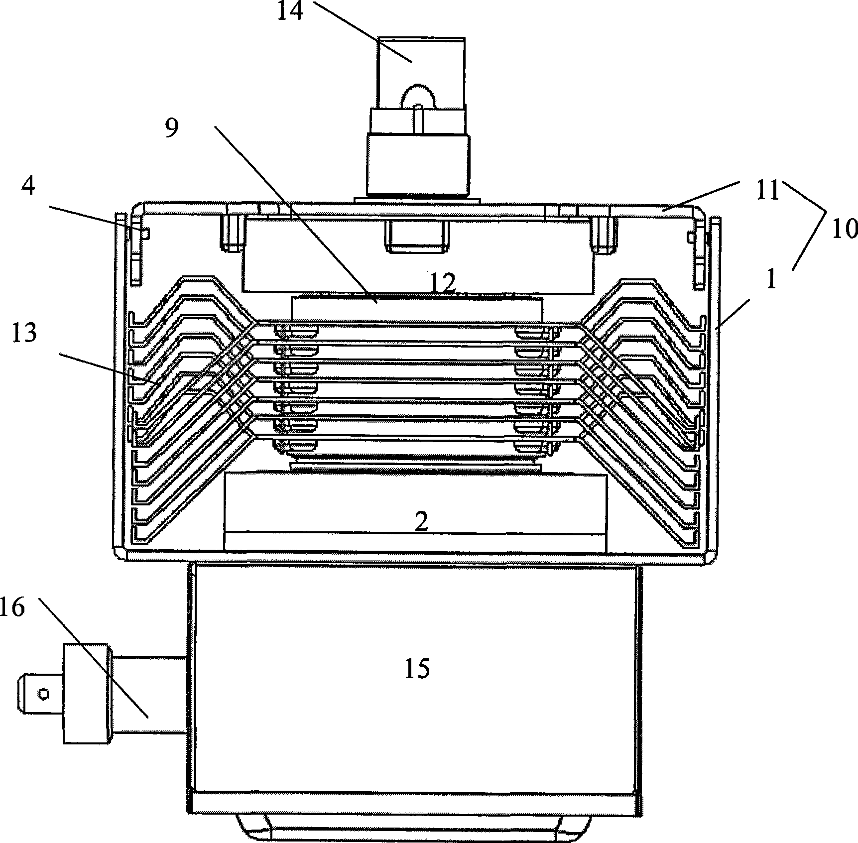
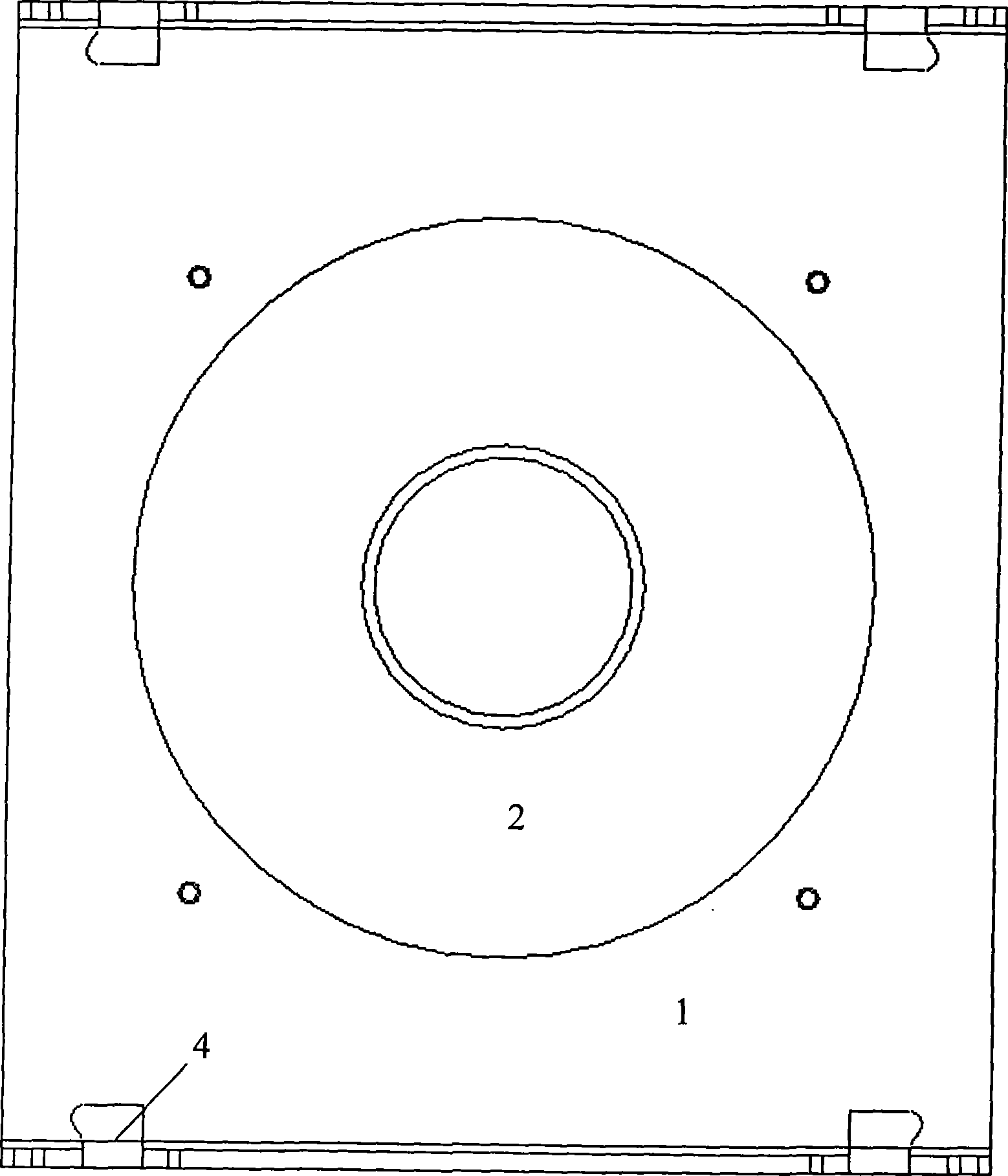
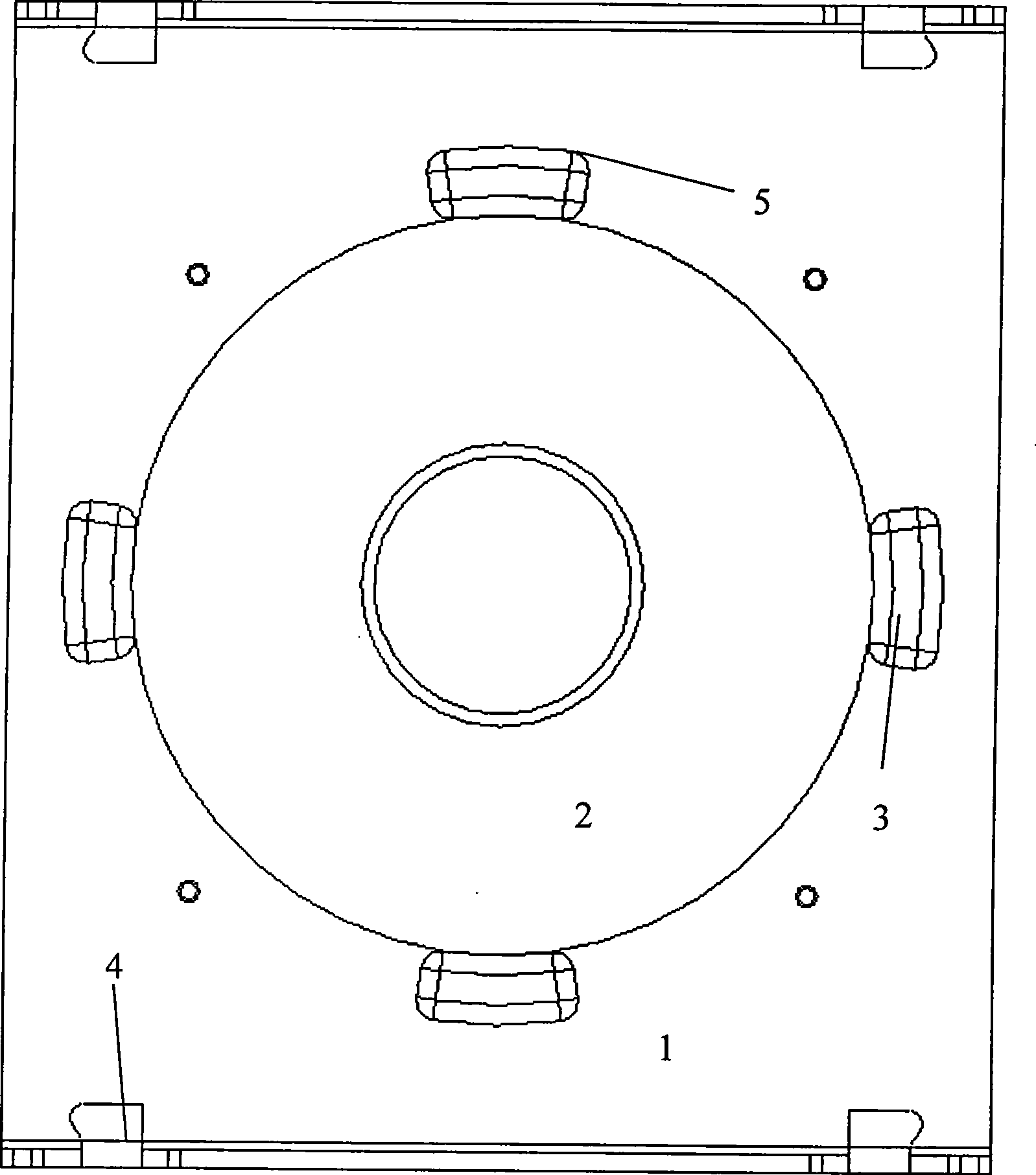
[0023] The magnetron where the upper and lower plates are used for the magnetron of the present invention is the same as the prior art. The yoke 10 is formed by connecting the upper plate 11 and the lower plate 1, and is roughly in the shape of a square box with openings on both sides. The top surface of the upper plate 11 All be square with the bottom surface of lower plate 1, the side wall of upper plate 11 is shorter, and the side wall of lower plate 1 is higher, and correspondingly be provided with connecting portion 4 on the side wall of upper and lower plate, connecting portion 4 connects upper, lower plate. The lower plate is combined to form a yoke 10, and the inside of the yoke 10 is equipped with an anode assembly and a cathode assembly.

[0024] The anode assembly includes an anode ...


PUM


Abstract

The invention discloses a magnetron used upper / lower plate including a magnetic yoke and a wave filter box. The magnetic yoke is formed by combining an upper plate with a lower plate; an upper magnet, a lower magnet, a positive pole component and a negative pole component are arranged in the magnetic yoke; a plurality of positioning grooves are formed on the inner faces of the upper plate and the lower plate; and the positioning grooves are formed by pressing the upper plate and the lower plate before installation and protruding inwards. The two ends of each groove, which are on the contact surfaces with the upper magnet and the lower magnet, are retracted inwards to form curved surfaces; and lead angles are formed on the top surfaces of the positioning grooves, thereby facilitating processing and becoming stronger. More than three lead angles are arranged, and the number is most preferably four. Through pressing the four positioning grooves, the magnetron used upper / lower plate ensures that the magnets can not move in the horizontal direction, the magnets can be positioned more precisely, and the magnetron can have good concentricity.

Description

technical field [0001] The invention relates to a magnetron, in particular to upper and lower plates for the magnetron. Background technique [0002] The prior art magnetron uses upper and lower plates, such as figure 1 with figure 2 As shown, the yoke 10 is formed by connecting the upper plate 11 and the lower plate 1. It is roughly in the shape of a square box with two sides open. The top surface of the upper plate 11 and the bottom surface of the lower plate 1 are both square. The side walls of the upper plate 11 are relatively Short, the side wall of the lower plate 1 is relatively high, the side walls of the upper and lower plates are correspondingly provided with a connecting part 4, the connecting part 4 combines the upper and lower plates to form a yoke 10, and the inside of the yoke 10 is equipped with Anode and cathode assemblies. A filter box 15 opening downward is connected to the bottom of the lower plate 1, and the choke coil in the filter box 15 can attenu...

Claims


Application Information

Patent Timeline
IPC IPC(8): H01J23/00
Inventor 孙宁
Owner LG ELECTRONICS (TIANJIN) APPLIANCES CO LTD
Why Eureka
Try Eureka