A. C. Power generator

A technology for alternators and circuit boards, applied to synchronous generators, electromechanical devices, electrical components, etc., which can solve the problem of increased cooling wind resistance, the first unidirectional energized element body and the second unidirectional energized element body Decreased cooling performance, large wind noise and other issues, to achieve the effect of reducing resistance and wind noise

Active Publication Date: 2012-03-21
MITSUBISHI ELECTRIC CORP
View PDF1 Cites 1 Cited by
  • Summary
  • Abstract
  • Description
  • Claims
  • Application Information

AI Technical Summary

Problems solved by technology

[0006] In the conventional rectifier of the vehicle alternator, the first terminal of the first unidirectional current-carrying element body is positioned at a predetermined position on one surface of the joint and fixed by welding, and then the second unidirectional The second terminal of the current-carrying element body is positioned at a specified position on the other side of the joint and then fixed by welding, so that the two sides of the joint are used in the connection between the first terminal and the second terminal and the joint, and there is a connection here. Problems with poor workability
[0007] In addition, since the inner diameter side end of the joint protrudes radially inward from the molded resin part, the protruding part of the joint increases the resistance to the cooling air generated by the rotation of the fan fixed on the side of the rotor, and the first unidirectional The cooling performance of the unidirectionally energized element body and the second unidirectionally energized element body is reduced, and there is also a problem of large wind noise

Method used


Image

  • A. C. Power generator
  • A. C. Power generator
  • A. C. Power generator

Examples


Embodiment Construction

[0018] Hereinafter, each embodiment of the present invention will be described with reference to the drawings, but the same or corresponding parts and locations will be described with the same reference numerals in each of the drawings.

[0019] Embodiment 1

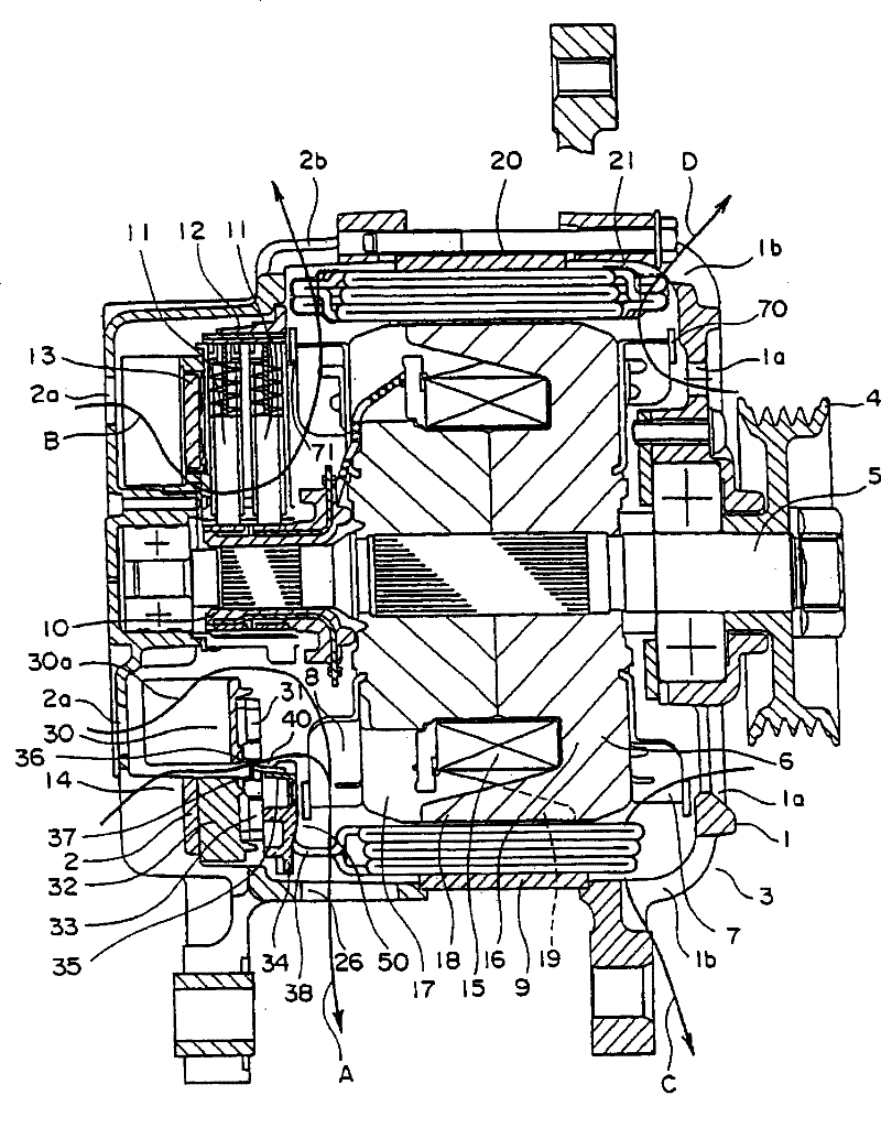
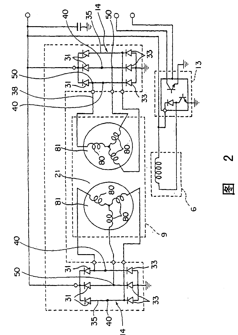
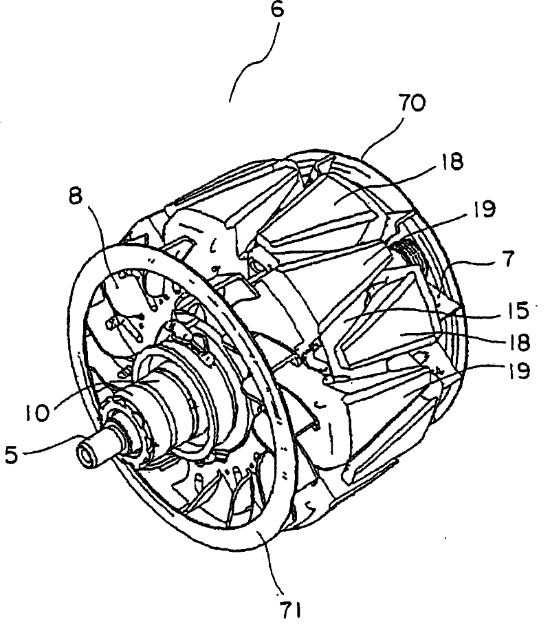
[0020] figure 1 is a side sectional view of a vehicle alternator (hereinafter simply referred to as an alternator) according to Embodiment 1 of the present invention, figure 2 yes figure 1 The circuit diagram of the alternator, image 3 yes means figure 1 A perspective view of the rotor 6.

[0021] In this alternator, a shaft 5 , to which a pulley 4 is fixed at one end, is provided in a casing 3 composed of an aluminum front end cover 1 and a rear end cover 2 , and is rotatable. On this shaft 5 a Randall-type rotor 6 is fixed. On the outer periphery of the rotor 6 , a stator 9 is fixed to the inner wall surface of the casing 3 so as to surround the rotor 6 .

[0022] On the other end of the shaft 5, a slip ring 1...


PUM


Abstract

The rectifier of an inventive AC generator comprises a first heat sink; first unidirectional conduction elements arranged at intervals on the surface of the first heat sink; a second heat sink provided spaced apart from the first heat sink, second unidirectional conduction elements arranged at intervals on the surface of the second heat sink; and a circuit board having terminals connected to constitute a bridge circuit with regard to the first unidirectional conduction elements and the second unidirectional conduction elements. The first terminals of the first unidirectional conduction elements and the second terminals of the second unidirectional conduction elements are connected contiguously on the same surface of the terminals, respectively, to constitute terminal side joints. Consequently, connection workability is enhanced between the terminals and the first terminals of the first unidirectional conduction elements and the second terminals of the second unidirectional conduction elements.

Description

technical field [0001] The present invention relates to an alternator having a rectifier for rectifying an alternating current generated by a stator of a vehicle alternator mounted on a vehicle, for example, into a direct current. Background technique [0002] As a conventional vehicle alternator, it is known to have: a casing; a rotor fixed to the shaft provided in the casing and having a fan at the end; a fan installed so as to surround the rotor and generated by a rotating magnetic field from the rotor. A stator for alternating current; and a rectifier provided on the end side of the shaft and rectifying the above-mentioned alternating current generated by the stator, the rectifier includes: a first radiator; The configured first unidirectional current-carrying element body; the second radiator arranged radially outside the first radiator; the second unidirectional radiator arranged at a certain interval on the surface of the second radiator An energizing element body; a...

Claims


Application Information

Patent Timeline
Patent Type & Authority Patents(China)
IPC IPC(8): H02K19/22
CPCH02K11/046H02K11/05H02K5/22H02K9/22H02K13/10H02K9/227H02K9/06
Inventor 西谷昌一郎大桥笃志
Owner MITSUBISHI ELECTRIC CORP
Why Eureka
Try Eureka