
Optical connector, male connector housing for optical connector, and female connector housing for optical connector

a technology for optical connectors and housings, applied in the field of optical connectors, can solve the problems of increasing the size of the optical connector, the inability to provide the support rigidity of the male connector housing, so as to improve the engagement positional precision of the male and female connector housings, the workability of the connection is improved, and the support rigidity is sufficien

Inactive Publication Date: 2015-08-25
FURUKAWA ELECTRIC CO LTD +1
View PDF17 Cites 0 Cited by
  • Summary
  • Abstract
  • Description
  • Claims
  • Application Information

AI Technical Summary

Benefits of technology

[0022]The present invention provides an optical connector, a male connector housing for the optical connector and a female connector housing for the optical connector, by which the workability of connection is improved and a sufficient level of supporting rigidity of the male connector housing is provided to stabilize the engagement state of the male and female connector housings while a size increase of the optical connector is suppressed, so that the engagement positional precision of the male and female connector housings is improved and high quality transmission characteristics are maintained for a long time.

Problems solved by technology

Unless the convexed and concaved parts of the male connector housing and the convexed and concaved parts of the female connector housing are in contact with each other along a sufficient area size, a sufficient level of supporting rigidity of the male connector housing cannot be provided after the male connector housing is inserted.
This results in a size increase of the optical connector.

Method used


Image

  • Optical connector, male connector housing for optical connector, and female connector housing for optical connector
  • Optical connector, male connector housing for optical connector, and female connector housing for optical connector
  • Optical connector, male connector housing for optical connector, and female connector housing for optical connector

Examples


Embodiment Construction

[0038]An embodiment of the present invention will be described with reference to the drawings.

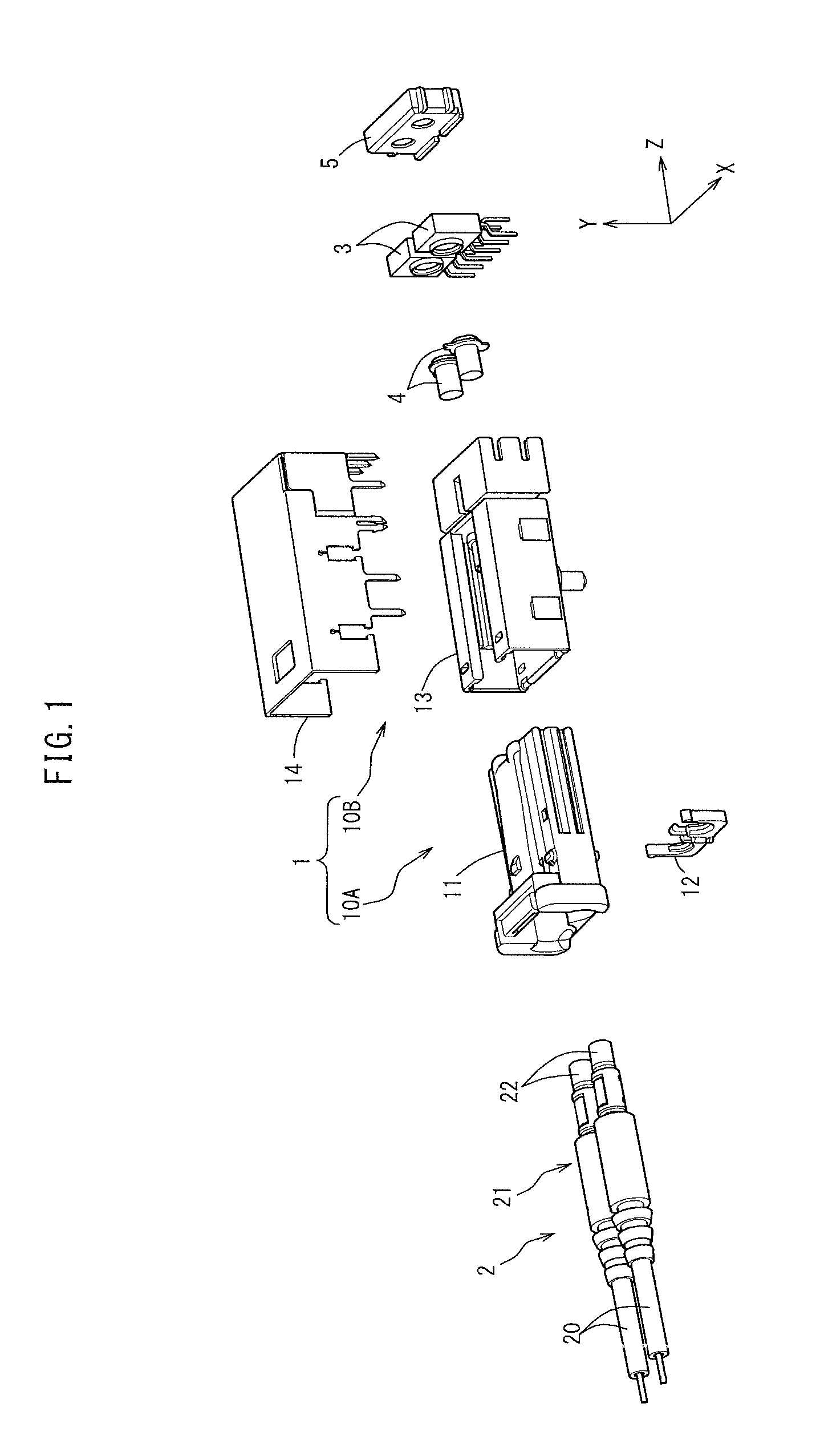
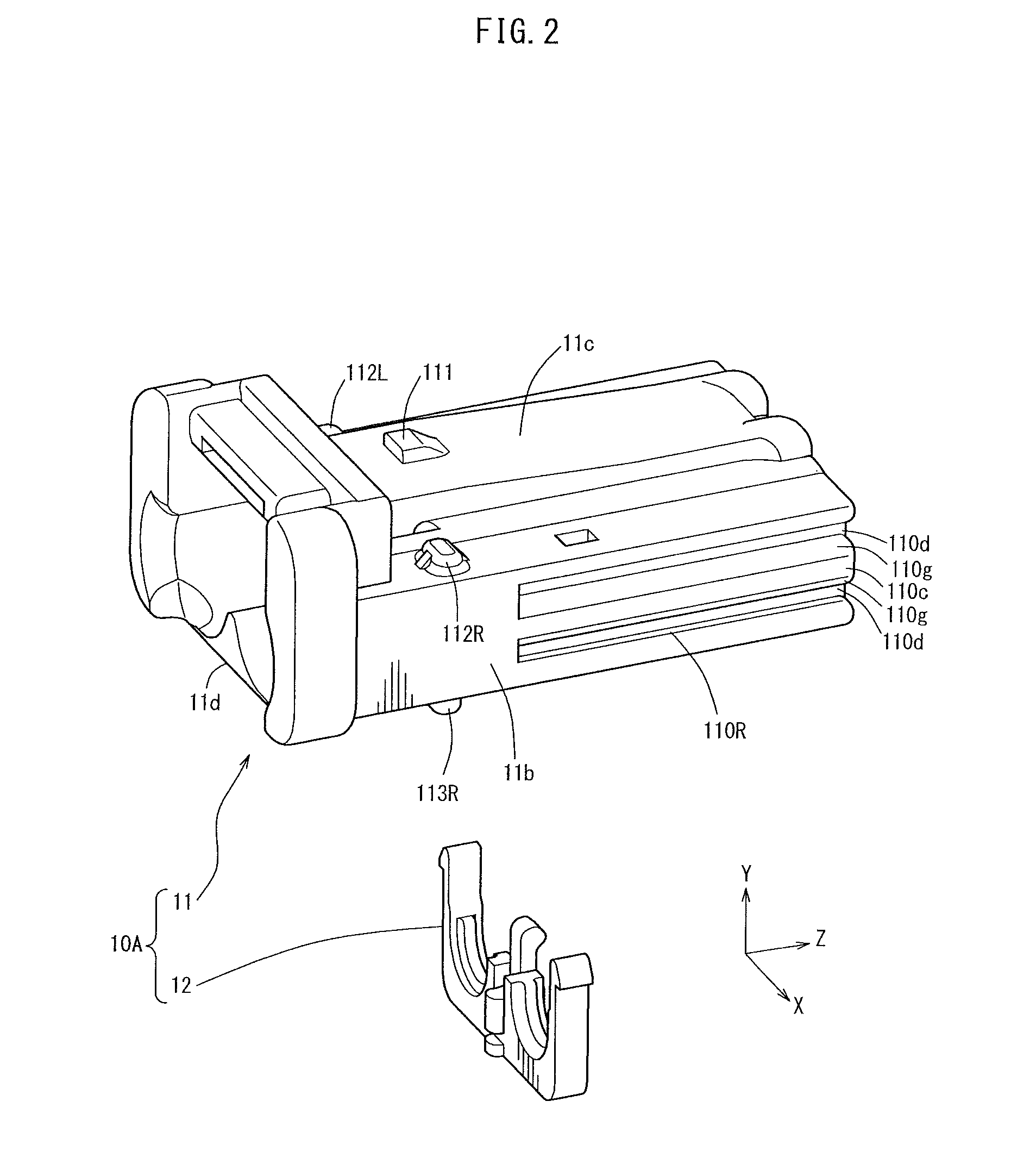
[0039]FIG. 1 is an exploded isometric view showing how a terminal-attached optical fiber cable 2 and FOTs (Fiber Optical Transceivers) 3 are connected to each other. FIG. 2 is an exploded isometric view of a male connector 10A. FIG. 3 is a rear view of the male connector 10A as seen from a leading end thereof when the male connector 10A is inserted into a female connector 10B.

[0040]FIG. 4 is an exploded isometric view of the female connector 10B. FIG. 5 is a plan view of a female connector housing 13. FIG. 6 is a front view of the female connector housing 13 as seen from the side on which a male connector housing 11 is inserted thereinto.

[0041]FIG. 7 shows steps of fixing a metal case 14 to the female connector housing 13. FIG. 8 is a cross-sectional view showing a state where an engageable concaved part 142 of the metal case 14 and an engageable convexed part 130 of the female connector ho...


PUM

PropertyMeasurementUnit
widthaaaaaaaaaa
structureaaaaaaaaaa
workabilityaaaaaaaaaa

Abstract

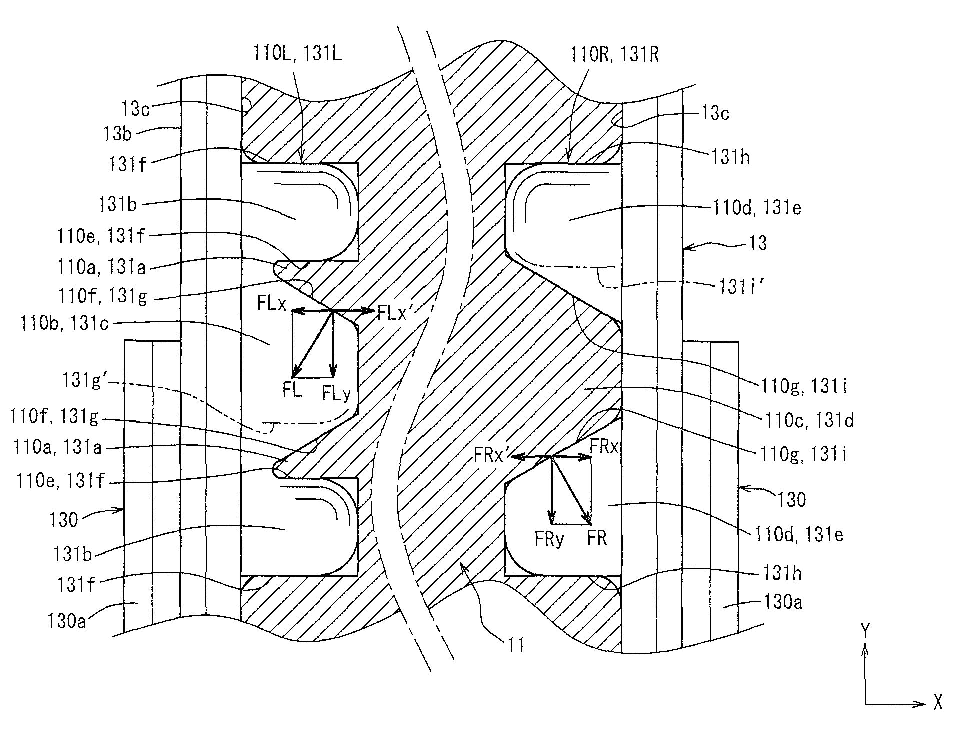
Guiding convexed and concaved parts provided on inner side surfaces of a female connector housing have inclining surfaces inclining with respect to a direction perpendicular to the inner side surfaces; whereas guided convexed and concaved parts provided on outer side surfaces of a male connector housing have inclining surfaces facing the inclining surfaces of the guiding convexed and concaved parts.

Description

TECHNICAL FIELD[0001]The present invention relates to an optical connector for an optical fiber cable forming an optical transmission path usable for transmitting information signals such as control signals, image signals, audio signals and the like, a male connector housing for the optical connector, and a female connector housing for the optical connector.BACKGROUND ART[0002]Recently, as the amount of communication information such as control signals, image signals, audio signals and the like transmitted in vehicles is increased, optical fiber cables, for example, are used for transmission paths for transmitting the information signals instead of conventional metal cables.[0003]As an element for connecting terminal-attached optical fiber cables which are related members forming an optical transmission path (optical transmission path-related members) to each other (so-called wire-to-wire connection) or for connecting a terminal-attached optical fiber cable to a known FOT (Fiber Opt...

Claims


Application Information

Patent Timeline
Patent Type & Authority Patents(United States)
IPC IPC(8): G02B6/40G02B6/42G02B6/38
CPCG02B6/4256G02B6/423G02B6/426G02B6/4292G02B6/389
Inventor KONDO, TOSHIKUNIENOMOTO, NORITSUGU
Owner FURUKAWA ELECTRIC CO LTD
Learn More