
Transcatheter coronary sinus mitral valve annuloplasty procedure and coronary artery and myocardial protection device

a technology of mitral valve and annuloplasty procedure, which is applied in the field of annuloplasty, can solve the problems of limiting drawbacks of the trans-sinus approach, affecting the usefulness of the coronary sinus annuloplasty, and affecting the function of the coronary sinus valve, so as to reduce unwanted effects and alter the shape of the heart or valv

Active Publication Date: 2012-07-03
UNITED STATES OF AMERICA
View PDF42 Cites 37 Cited by
  • Summary
  • Abstract
  • Description
  • Claims
  • Application Information

AI Technical Summary

Benefits of technology

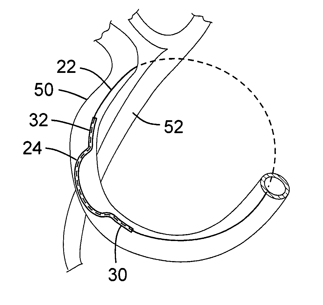
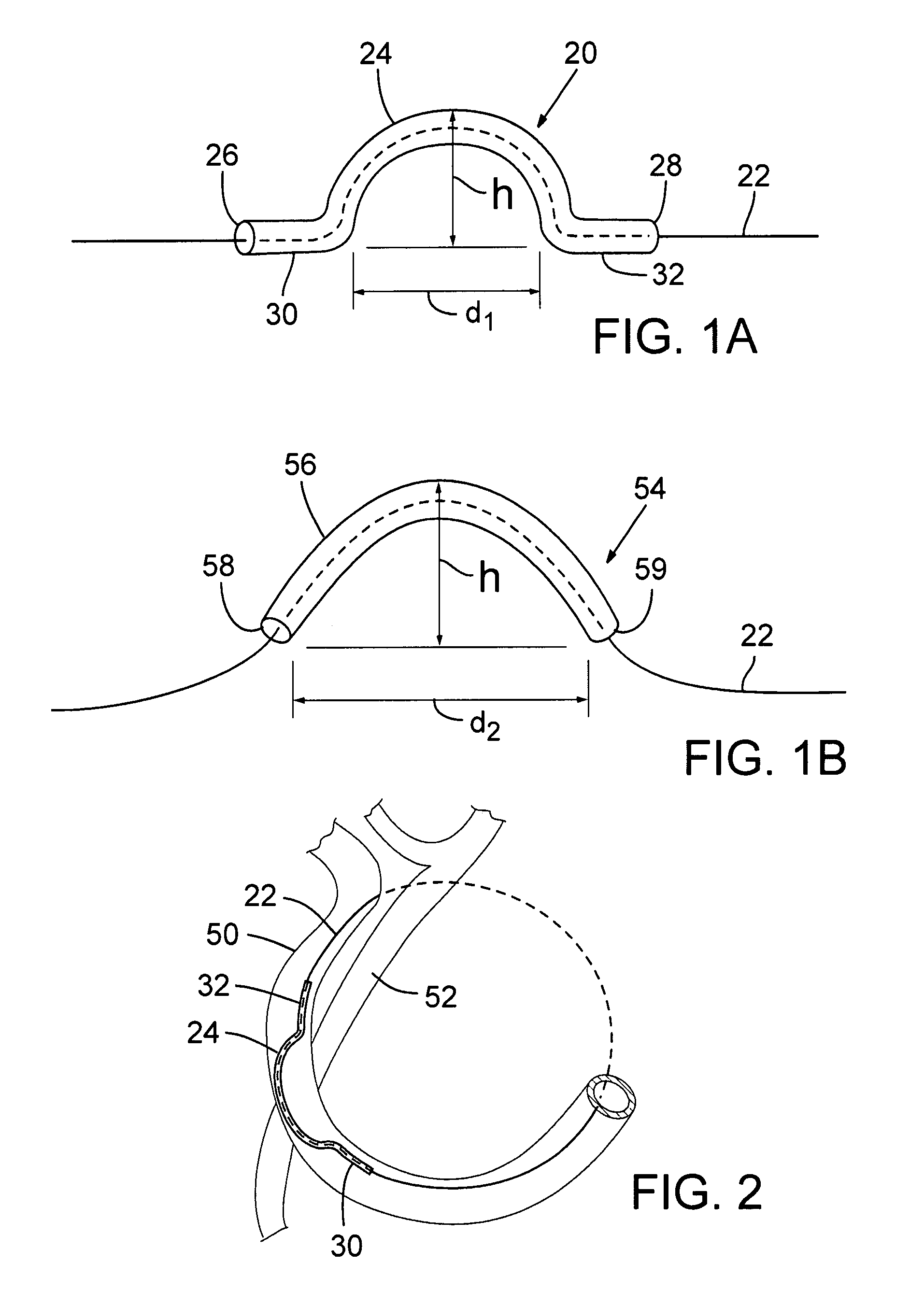
The patent describes a device and method for protecting the heart from damage during a heart valve repair procedure called mitral valve annuloplasty. The device is placed in the coronary sinus to prevent pressure from constricting the coronary artery branches and inducing myocardial ischemia or infarction. The device is a surgically sterile bridge that supports an annuloplasty element and prevents it from compressing the underlying coronary artery branches. The device can be used in combination with an endovascular catheter to introduce the annuloplasty element and protective device into the heart. The technical effect of the device is to improve the function of the mitral valve without impairing coronary blood flow.

Problems solved by technology

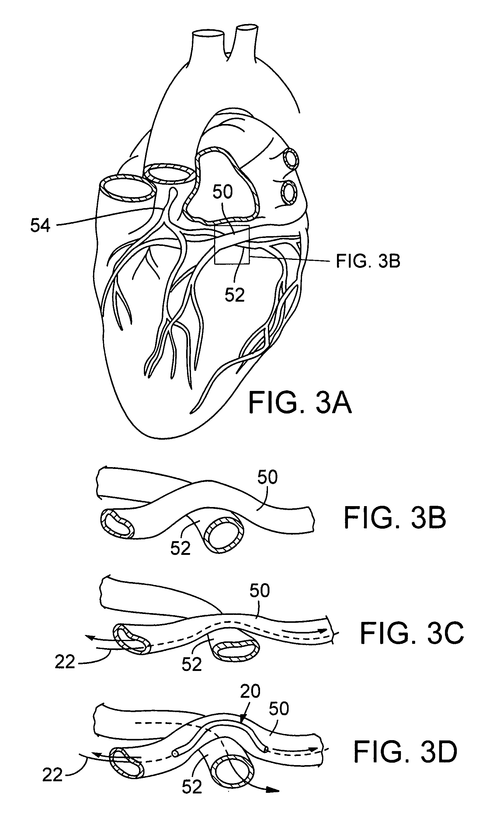
Trans-sinus approaches that use the cerclage technique or other indwelling coronary sinus prostheses can have limiting drawbacks, however, because the coronary sinus and its branches have now been found to cross the outer diameter of major coronary arteries in a majority of humans.
As a result, pressure applied by any prosthetic device in the coronary sinus (such as tension on the annuloplasty device) can compress the underlying coronary artery and induce myocardial ischemia or infarction.
In a majority of humans, the coronary vein crosses over the left circumflex artery, which has limited the usefulness of coronary sinus annuloplasty.

Method used


Image

  • Transcatheter coronary sinus mitral valve annuloplasty procedure and coronary artery and myocardial protection device
  • Transcatheter coronary sinus mitral valve annuloplasty procedure and coronary artery and myocardial protection device
  • Transcatheter coronary sinus mitral valve annuloplasty procedure and coronary artery and myocardial protection device

Examples


example 1

Annuloplasty using Protective Device with Percutaneous Transluminal Coronary Angioplasty Wire for Cerclage

[0078]This Example demonstrates the efficacy of one embodiment of the protective device in protecting the coronary artery from compression during trans-sinus annuloplasty. In this Example, the protective device was constructed of a stainless-steel hypotube (FIG. 5). A 57 kg Yucatan pig was anesthetized, and after obtaining vascular access in the right jugular vein, the femoral vein, and the femoral artery, an annuloplasty wire (0.014 conventional percutaneous transluminal coronary angioplasty (PTCA) wire) was positioned around the mitral annulus to form a cerclage using the method described herein in which tensioning material passes through the coronary sinus over a coronary artery. FIG. 6 shows the left coronary angiogram of the subject with the wire in position, but before tension was applied.

[0079]After encircling the mitral annulus with the annuloplasty wire via the coronary...

example 2

Annuloplasty using an Alternate Embodiment of the Protective Device

[0081]To quantify the protective ability of the device, the pressure in the left circumflex artery was measured using a conventional coronary pressure wire (Radi pressure wire). A 65 kg Yucatan pig was anesthetized, and after obtaining vascular access in the right jugular vein, the femoral vein, and the femoral artery, an annuloplasty wire (0.014 conventional PTCA wire) was positioned around the mitral annulus to form a cerclage essentially as described in Example 1. After placing the cerclage, but before tension was applied, the pressure wire was positioned at a site in the left circumflex artery that was distal to the point where the cerclage passed over the coronary artery. Distal coronary pressure was measured while tension was applied with and without the protective device in place over the left circumflex artery branch. The protective device ameliorated the reduction in distal coronary artery pressure caused by...

example 3

Annuloplasty using a Third Embodiment of the Protective Device

[0082]This Example demonstrates the efficacy of another alternate embodiment of the protective device. For this Example, the protective device was modified to augment the height of the central curve, and thereby further protect the coronary artery from compression during annuloplasty. A 74 kg Yucatan pig was anesthetized, and after obtaining vascular access in the right jugular vein, the femoral vein, and the femoral artery, an annuloplasty wire (0.014 conventional PTCA wire) was positioned around the mitral annulus to form a cerclage essentially as described in Example 1. After placing the cerclage, the end of cerclage wire from the right jugular vein was fixed and graded tensions of 0 grams, 200 grams, 400 grams and 600 grams were applied through the femoral end of a cerclage wire with and without the protective device in position over the left circumflex artery branch. FIG. 9 is a series of angiograms that show the eff...


PUM


Abstract

A protective device or bridge (20) comprising a central arch (24) is suitable to be placed between an annuplasty device placed in the coronary sinus and an underlying coronary artery to inhibit transmission of compressive force on the coronary artery by the annuplasty device.

Description

CROSS-REFERENCE TO RELATED APPLICATIONS[0001]This is the U.S. National Stage of International Application No. PCT / US2007 / 023876 filed Nov. 13, 2007, which was published in English under PCT Article 21(2), which in turn claims the benefit of U.S. Provisional Application No. 60 / 858,716, filed Nov. 14, 2006 and U.S. Provisional Application No. 60 / 932,611 filed May 31, 2007, both of which are incorporated herein in their entirety.FIELD OF THE DISCLOSURE[0002]The present disclosure relates to annuloplasty techniques and devices in which tensioning elements are placed in the coronary sinus to perform mitral valve annuloplasty and treat mitral valve regurgitation.BACKGROUND[0003]Mitral valve regurgitation is a common cardiac valve disorder that can be caused by a primary valvular problem (such as damaged valve leaflets) or functional problems that impair leaflet coaption. A common cause of functional mitral valve regurgitation is dilated cardiomyopathy caused by myocardial infarction, chro...

Claims


Application Information

Patent Timeline
Patent Type & Authority Patents(United States)
IPC IPC(8): A61F2/24
CPCA61F2/2451A61F2210/0014A61F2220/0075A61F2230/0045A61F2250/0065A61F2250/0037A61F2002/068A61F2/06A61M2025/0042A61M25/0041A61M2025/0059A61F2250/0004A61F2250/001
Inventor KIM, JUNE-HONGLEDERMAN, ROBERT J.KOCATURK, OZGUR
Owner UNITED STATES OF AMERICA
Learn More