
A. C. Power generator
An alternator and circuit board technology, which is applied to synchronous generators, electromechanical devices, electrical components, etc., can solve the problem of increased cooling wind resistance, poor connection workability, the first unidirectional energization element body and the second The cooling performance of the unidirectional energization element body is reduced, and the effect of reducing the resistance and wind noise is achieved.
- Summary
- Abstract
- Description
- Claims
- Application Information
AI Technical Summary
Problems solved by technology
Method used
Image

Examples
Embodiment Construction
[0018] Hereinafter, each embodiment of the present invention will be described with reference to the drawings, but the same or corresponding parts and locations will be described with the same reference numerals in each of the drawings.
[0019] Embodiment 1
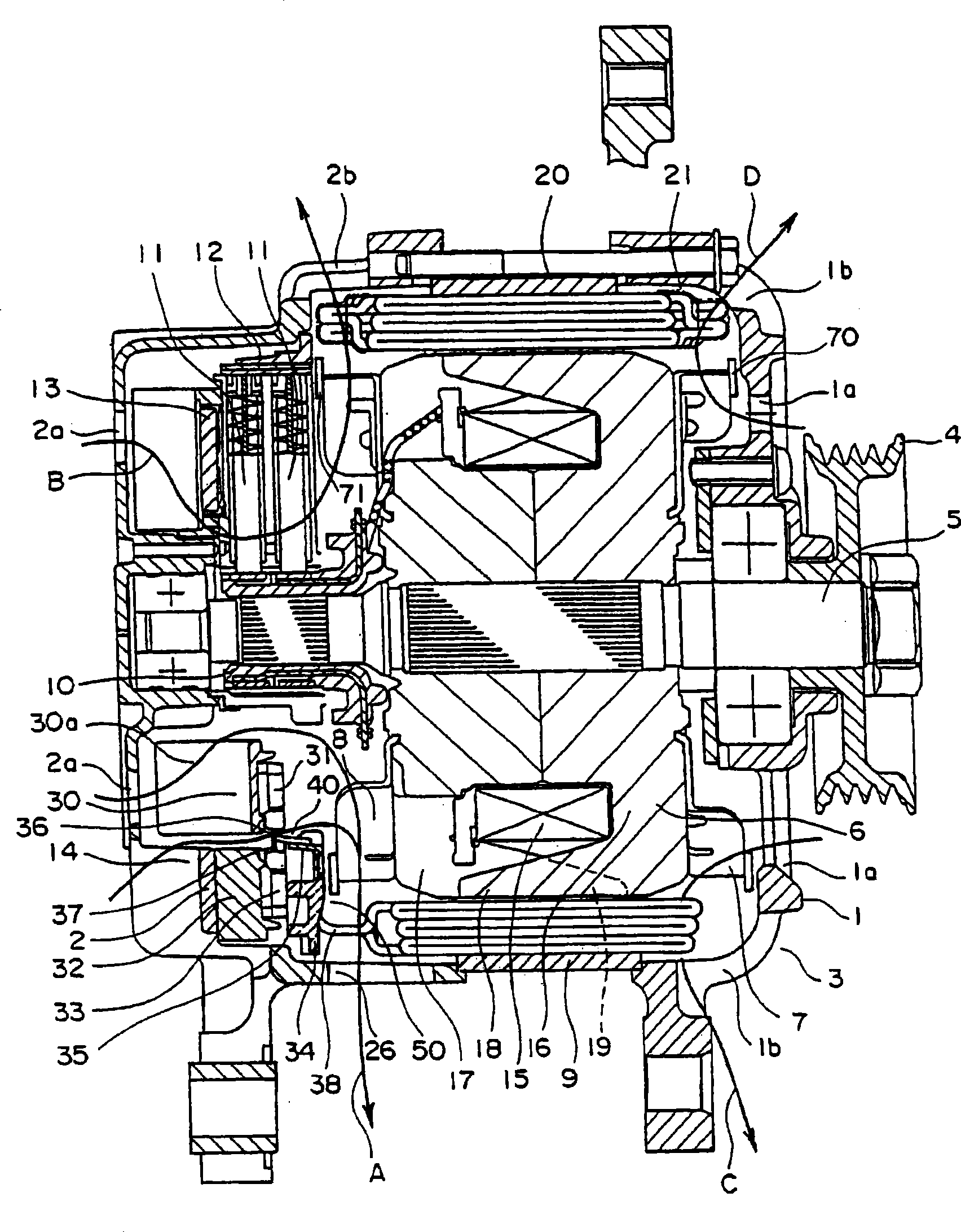
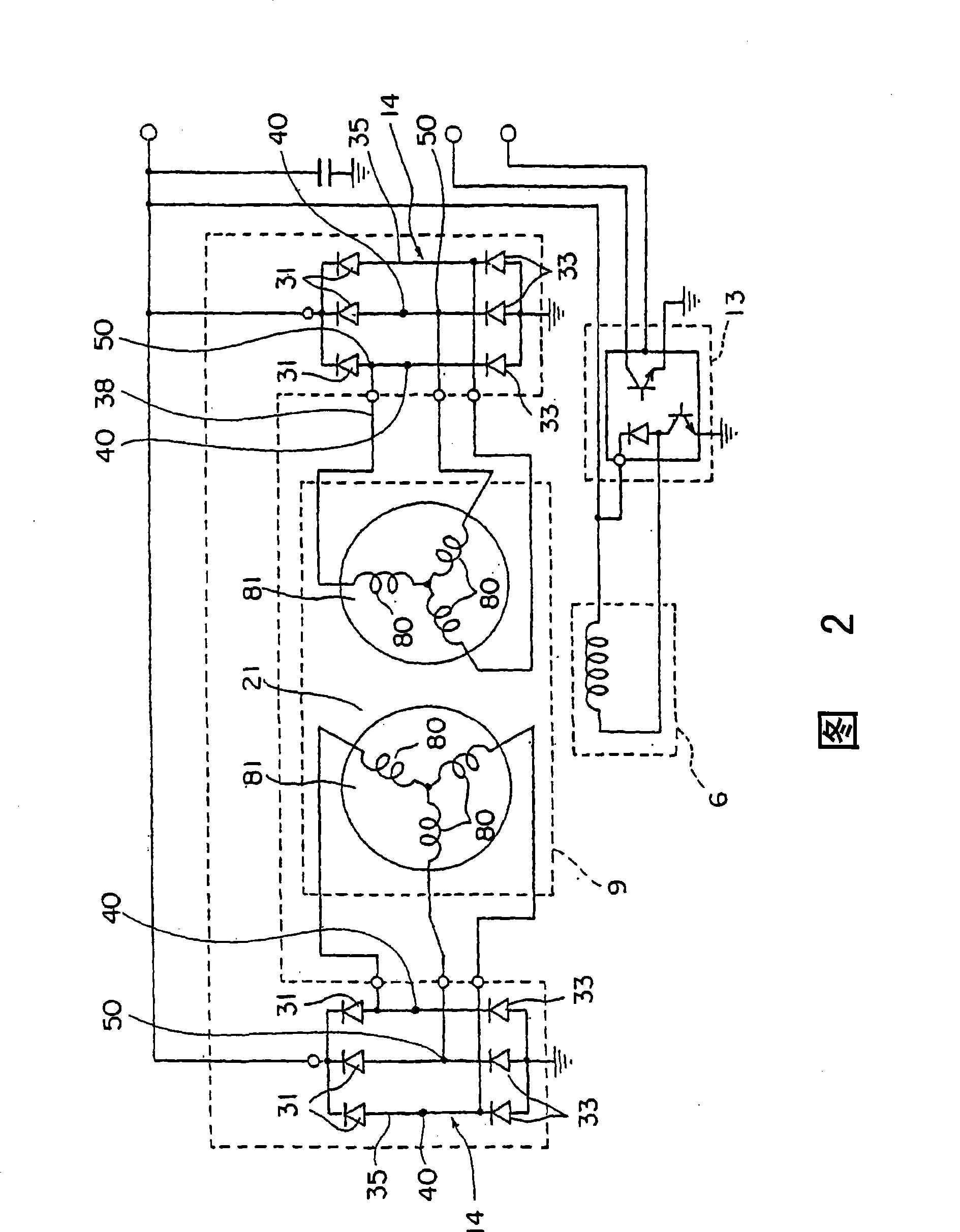
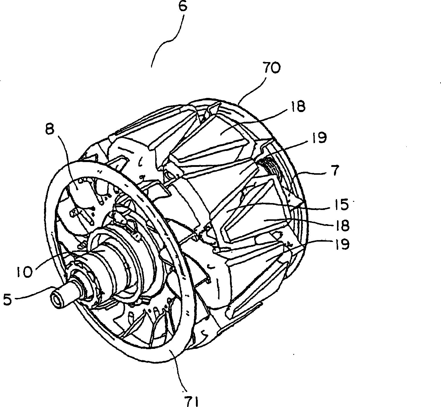
[0020] figure 1 is a side sectional view of a vehicle alternator (hereinafter, simply referred to as an alternator) according to Embodiment 1 of the present invention, and FIG. 2 is figure 1 The circuit diagram of the alternator, image 3 yes means figure 1 A perspective view of the rotor 6.
[0021] In this alternator, a shaft 5 , to which a pulley 4 is fixed at one end, is provided in a casing 3 composed of an aluminum front end cover 1 and a rear end cover 2 , and is rotatable. On this shaft 5 a Randall-type rotor 6 is fixed. On the outer periphery of the rotor 6 , a stator 9 is fixed to the inner wall surface of the casing 3 so as to surround the rotor 6 .
[0022] On the other end of the shaft 5, a slip ring 1...
PUM
 Abstract
Description
Claims
Application Information