Magnet-type generator

a generator and magnet-type technology, applied in the direction of windings, magnetic circuit rotating parts, magnetic circuit shape/form/construction, etc., can solve the problems of complicated arrangement of lead wires and remarkable inefficiency in workability viewpoint, and achieve the effect of suppressing the rattling of lead wires, shortening the separation distance, and improving vibration resistan

Active Publication Date: 2017-01-03
DENSO TRIM CO LTD
View PDF25 Cites 0 Cited by
  • Summary
  • Abstract
  • Description
  • Claims
  • Application Information

AI Technical Summary

Benefits of technology

[0010]In the present aspect, the lead wires are inserted into the through holes which are separately prepared corresponding to respective phases and connected with the outgoing wires of the coil via the metal connection terminal arranged near the through holes. Therefore, the lead wires inserted into the through holes can be connected to the metal connection terminal without arranging the lead wires for a long distance. Consequently, the workability of the connection work can be improved.
[0027]By using the magnet-type generator of the present invention, the workability to connect the lead wires with the outgoing wires of the coil can be improved and the vibration resistance of the lead wires can be improved.

Problems solved by technology

When using such thick lead wires, it is remarkably inefficient in viewpoint of workability to insert the lead wires of a plurality of phases into one through-hole and complicatedly arrange the lead wires.

Method used


Image

  • Magnet-type generator
  • Magnet-type generator
  • Magnet-type generator

Examples


Embodiment Construction

[0048]1. Embodiment

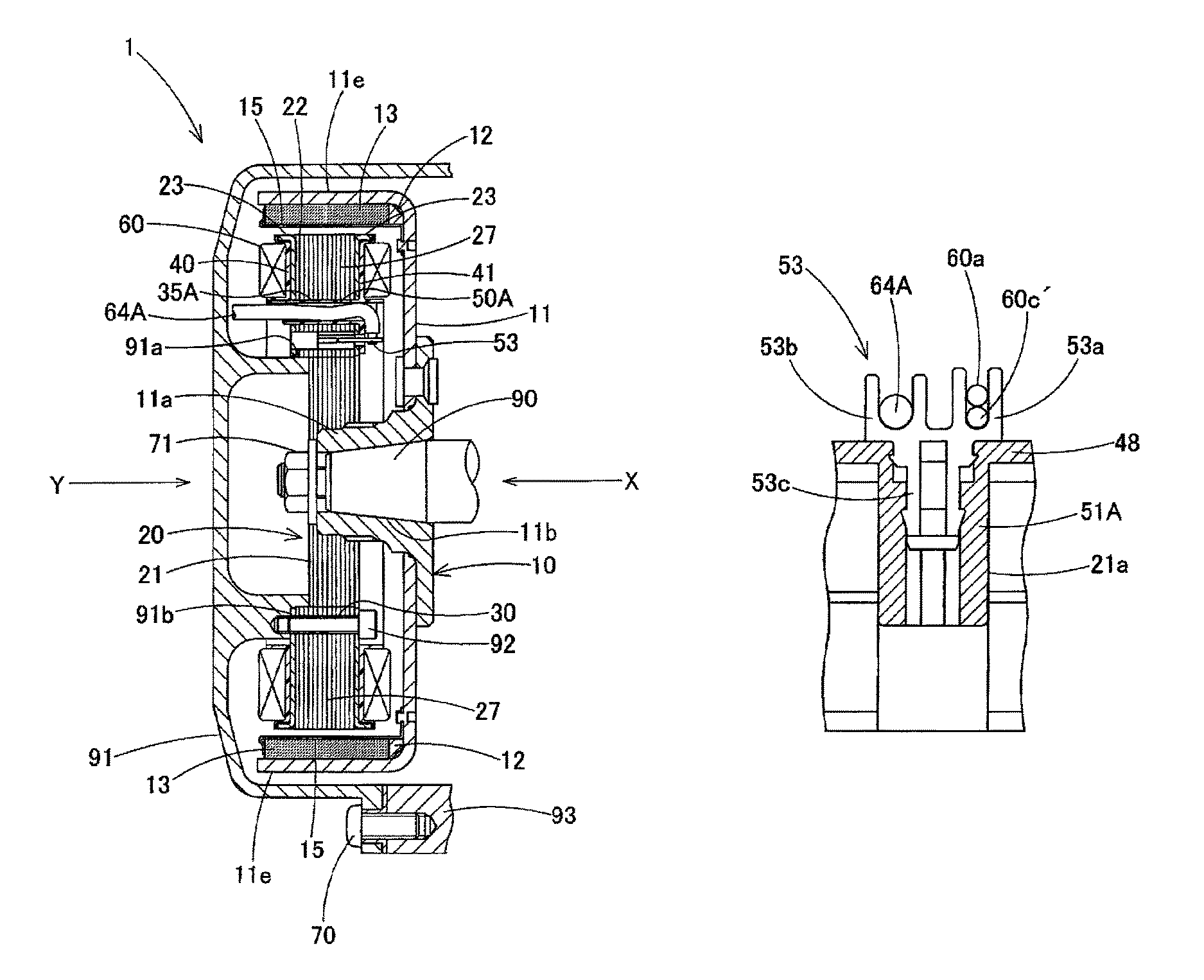
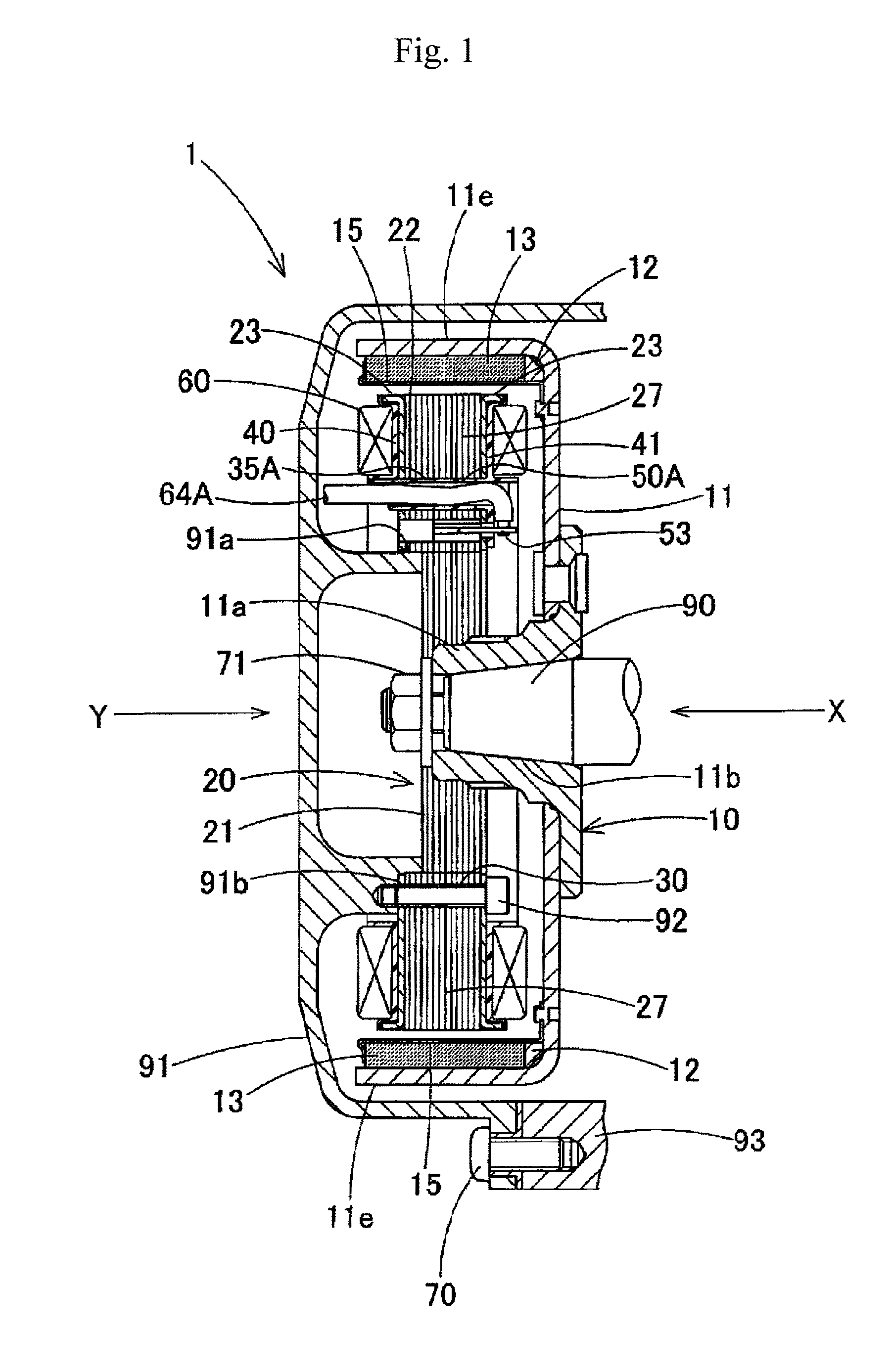
[0049]Hereafter, an embodiment of the present invention will be explained based on the drawings. FIG. 1 is a cross-sectional view of a three-phase magnet-type generator concerning an embodiment of the present invention. As shown in FIG. 1, a three-phase magnet-type generator 1 has a rotor 10 that is fixed to a crank shaft 90 of an engine and a stator 20 that is fixed to an engine cover 91 so as to be located at an inner peripheral side of the rotor 10. The engine cover 91 is fixed to an engine body 93 by clamping a screw 70. The number of poles of the rotor 10 is twenty, for example. The number of poles of the stator 20 is fifteen, for example.

[0050]The rotor 10 has a rotary member 11 made of a magnetic material. A tapered portion 11b formed at a boss portion 11a of the rotary member 11 is fit into an end of the crank shaft 90 and fixed by a bolt 71. A yoke is formed by a tubular-shaped outer peripheral portion 11e of the rotary member 11.

[0051]Inside the outer pe...


PUM


Abstract

A magnet-type generator 1 has a stator 20 having a stator core 21, bobbins 40, 41 and a coil 60. The stator core has through holes 35A, 35B, 35C passing through the stator core parallel to a rotation axis of the rotor so that lead wires 64A, 64B, 64C for outputting current generated at the magnet-type generator 1, which are corresponding to respective phases, are inserted into the through holes. The lead wires inserted into the through holes are connected with outgoing wires 60a, 60c′, 60b, 60a′, 60c, 60b′ of the coil at one side (clamping surface side) of the stator core 21 via a terminal (metal connection terminal) 53 fixed to a substrate portion (plate portion) 48 extending from the bobbin. The terminal is arranged near the through holes.

Description

CROSS-REFERENCES TO RELATED APPLICATIONS[0001]This Application claims the benefit of priority and is a Continuation application of the prior International Patent Application No. PCT / JP2013 / 052745, with an international filing date of Feb. 6, 2013, which designated the United States, and is related to the Japanese Patent Application No. 2012-027641, filed Feb. 10, 2012, the entire disclosures of all applications are expressly incorporated by reference in their entirety herein.BACKGROUND OF THE INVENTION[0002]1. Field of the Invention[0003]The present invention relates to a magnet-type generator mounted on an engine of a two-wheel vehicle (motorcycle), a buggy, a jet ski bike, or the like in order to charge a battery or for other purposes.[0004]2. Description of Related Art[0005]In stators of magnet-type generators having an outer rotor-inner stator configuration, as shown in FIG. 15, the following structure is adopted to connect outgoing wires of a coil with lead wires for outputting...

Claims


Application Information

Patent Timeline
Patent Type & Authority Patents(United States)
IPC IPC(8): H02K3/52H02K5/22H02K3/28H02K1/27H02K3/34H02K21/22
CPCH02K3/522H02K1/27H02K1/2786H02K3/28H02K3/345H02K5/225H02K21/22H02K2203/06H02K2203/12H02K2213/03H02K1/2791
Inventor HIKITA, TAKAHIKO
Owner DENSO TRIM CO LTD
Why Eureka
Try Eureka