Material receiving mechanism for conveying pipe fitting

A technology for conveying pipes and pipe fittings, which is applied in the direction of conveyors, conveyor objects, feeding devices, etc. It can solve the problems of bent pipes or pipe fittings being twisted and damaged, easy to insert under the rear swing arm, messy, etc., to achieve neat placement , to avoid the effect of pipe breaking and bending

Active Publication Date: 2009-04-01
OMS MASCH CO LTD
View PDF0 Cites 22 Cited by
  • Summary
  • Abstract
  • Description
  • Claims
  • Application Information

AI Technical Summary

Problems solved by technology

[0003] During actual use, the existing material receiving mechanism has the following disadvantages: (1), the elbow or pipe fitting is elongated, and its front end will bend downward after the elbow or pipe fitting is moved out to a certain length. When placed on the rack formed by multiple swing arms, the front end of the elbow or pipe fitting is easily inserted under the rear swing arm, causing the processed elbow or pipe fitting to be twisted and damaged; (2). Multiple bends or pipe fittings on the pipe machine are placed on the swing arm together. Since the upper surface of the swing arm must be smooth, multiple bends or pipe fittings are placed on the swing arm in disorder. When the cylinder drives the swing arm to rotate around the shaft After a certain angle, the elbows or pipe fittings on the swing arm are poured into the storage tank is also very messy, thus affecting the storage capacity of the storage tank

Method used


Image

  • Material receiving mechanism for conveying pipe fitting
  • Material receiving mechanism for conveying pipe fitting
  • Material receiving mechanism for conveying pipe fitting

Examples


Embodiment Construction

[0017] A further detailed description will be made below in conjunction with the accompanying drawings and embodiments of the present invention:

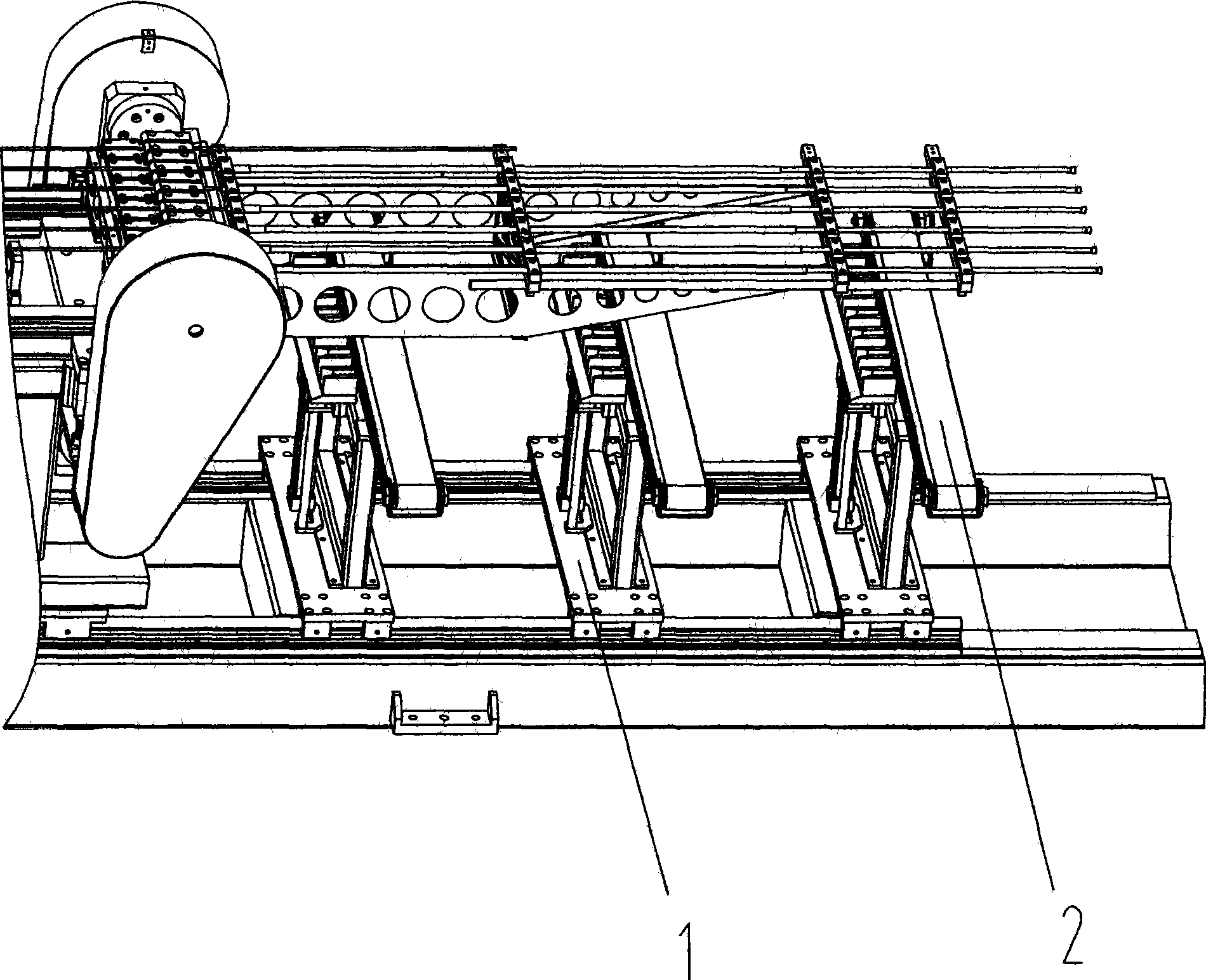
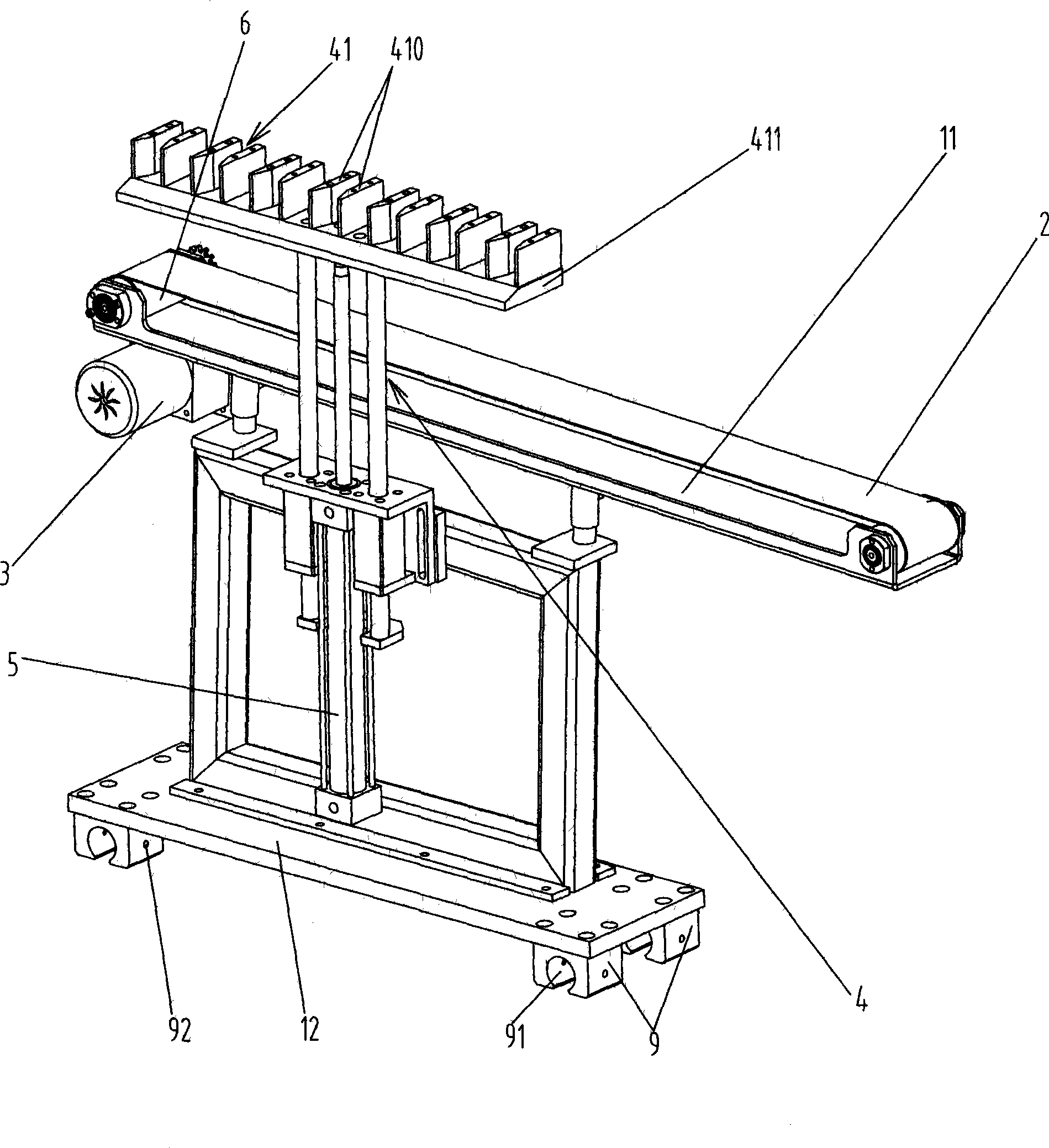
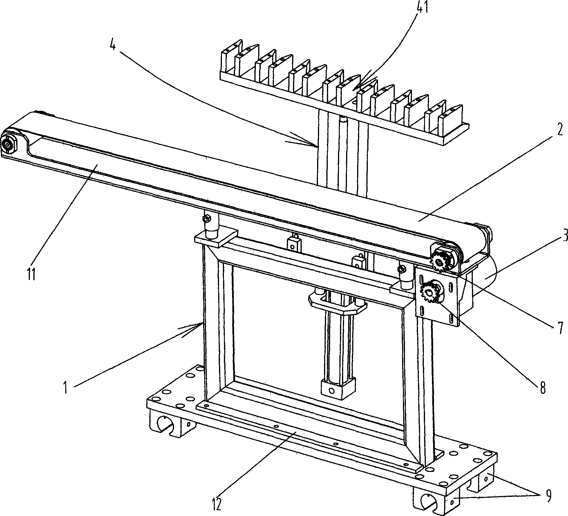
[0018] As shown in the figure, the material receiving mechanism for conveying pipe fittings includes a conveyor belt 2 installed on a bracket 1 and a first drive 3 that drives the conveyor belt to rotate. One side of the conveyor belt 2 is provided with a The pipe fittings are sent to the material receiving frame 4 on the conveyor belt 2, the upper end of the material receiving frame 4 is provided with a plurality of clamping positions 41 for placing the pipe fittings, and the second driving member 5 for promoting its movement is installed under the material receiving frame 4, the present invention Among them, the upper end of the material receiving frame 4 is provided with a material receiving plate 411, and the clamping position 41 is a material receiving trough formed by two vertical baffles 410 and the material receiving plate 41...


PUM


Abstract

The invention discloses a material receiving mechanism used for conveying pipes, comprising a conveyor belt which is arranged on a bracket and a motor which drives the conveyor belt to rotate; one side of the conveyor belt is provided with a material receiving frame which can move upwards and downwards and convey the pipes onto the conveyor belt; the upper end of the material receiving frame is provided with a plurality of clamps which are used for arranging pipes; a cylinder used for pushing the material receiving frame is arranged below the material receiving frame. The material receiving mechanism has the beneficial effects that the upper end of the material receiving frame is provided with a plurality of clamps used for arranging pipes, thus ensuring that the pipes can be conveyed stably and enter material receiving troughs corresponding to each pipe without impact during the material receiving process and the blanking is arranged orderly; the cylinder pushes the material receiving frame to move downwards; the pipes can drip on the conveyor belt in running stably and orderly and can move forwards together with the conveyor belt; finally, the pipes can be stably and orderly sent to the material storage trough which is arranged at one side of the conveyor belt; the transmission of the pipes is stable and orderly.

Description

[technical field] [0001] The invention relates to a conveying device, in particular to a material receiving mechanism for conveying pipe fittings. [Background technique] [0002] The traditional elbow or pipe fitting material receiving mechanism is composed of a rotating shaft and a swing arm. The cylinder drives multiple swing arms to rotate around the rotating shaft at the same time to complete material receiving and transfer. The material receiving process is as follows: processed elbow or other pipe fittings After being transported from the machine tool, the bent pipe or pipe fittings are placed on the receiving rack formed by multiple swing arms, and after the swing arm is driven by the cylinder to rotate a certain angle around the rotating shaft, the bent pipe or pipe fittings on the swing arm slide down to the storage on one side. In the trough. [0003] During actual use, the existing material receiving mechanism has the following disadvantages: (1), the elbow or pi...

Claims


Application Information

Patent Timeline
Patent Type & Authority Applications(China)
IPC IPC(8): B65G47/06B65G15/60B65G23/24B21D43/00B21D43/20
Inventor 龙晓斌
Owner OMS MASCH CO LTD
Why Eureka
Try Eureka