
Washer and rotary drum control electric installation

A technology for washing machines and drums, which is applied in the field of washing machines and rotating drums to control electrical equipment, can solve the problems of expensive acceleration sensors, unbalanced distribution of detected clothes, and low prediction accuracy.

Inactive Publication Date: 2010-12-29
PANASONIC CORP
View PDF1 Cites 0 Cited by
  • Summary
  • Abstract
  • Description
  • Claims
  • Application Information

AI Technical Summary

Problems solved by technology

[0005] However, in the conventional washing machine as described above, when detecting the unbalanced laundry during the dehydration process, the unbalanced distribution of the laundry is detected during the low-speed rotation during the dehydration process.
Therefore, there is the following problem: the moisture contained in the clothing is not completely detached and is easily affected by fibers or clothing that are easy to contain water, fibers or clothing that are not easy to contain water, etc., the material of the fibers, the type and quantity of the clothing, and dehydration at a high speed. Prediction of vibrations during rotation is less accurate
However, in the rotation range above the medium speed, the influence of the dynamic unbalance that cannot be detected in the low-speed rotation becomes large, and the drum rotates relative to the center of gravity due to the dynamic unbalance, thereby increasing the vibration.
Therefore, there is a problem that the judgment criterion for the transition to the high-speed dehydration rotation can also be lowered, but when the judgment criterion is lowered in this way, the number of cases where it is judged that dehydration is not possible increases, and it is difficult to judge whether the transition to the dehydration operation is possible.
However, the acceleration sensor itself is expensive, so there is a problem that the equipment cost increases

Method used


Image

  • Washer and rotary drum control electric installation
  • Washer and rotary drum control electric installation
  • Washer and rotary drum control electric installation

Examples


Embodiment approach

[0018] Hereinafter, an embodiment of the present invention will be described with reference to the drawings. In addition, this invention is not limited to this embodiment.

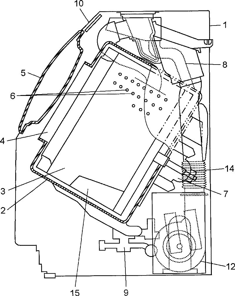
[0019] figure 1 It is a cross-sectional view showing a schematic structure of a front-loading washing machine according to an embodiment of the present invention. exist figure 1 In the washing machine main body 1, the water tank 2 is supported in a suspended state by a suspension structure (not shown). A drum 3 formed in a cylindrical shape with a bottom is rotatably supported in the water tank 2, and the axis direction of the drum 3 is inclined downward from the front side to the back side. On the front side of the water tub 2 is formed a clothes inlet and outlet 4 connected to the opening end of the drum 3 . Laundry can be taken out and put into the drum 3 through the clothes inlet and outlet 4 by opening and closing the door 5 which closes the opening of the upwardly inclined surface provided on the...


PUM


Abstract

The present invention provides a washing machine and an electrical device for controlling rotating roller, wherein the washing machine comprises the following components: a motor (7) which drives the rotation of drum (3) containing the washed object; a rotation speed detecting part (14) which detects the rotation speed of motor (7); and a controlling part (31) which controls the rotation of motor(7) according to the detection output of rotation speed detecting part (14), wherein, the controlling part (31) measures the accumulated acceleration torque in a rotation speed raising period when the rotation speed of drum (3) raises from a preset regulated rotation speed N1 to a preset regulated rotation speed N2, and controls the rotation of motor according to the accumulated acceleration torque. Thereby the unbalanced state of clothes in the drum (3) can be detected with a high precision for driving the motor (7) with a low vibration.

Description

technical field [0001] The present invention relates to a washing machine which washes the laundry contained in the rotating drum by rotating and driving the rotating drum arranged in the water tank, and the rotating drum controlling electric equipment. Background technique [0002] The conventional drum-type washing machine disclosed in Japanese Patent Application Laid-Open No. 2007-68813 includes: a drum that accommodates laundry and rotates; and a water tank in which the drum is rotatably installed and elastically supported. Inside the main body of the washing machine. In addition, a motor for rotationally driving the drum, and a rotational speed detection device for detecting the rotational speed of the motor are provided. A control unit is further provided which controls the rotation of the motor based on the detection output of the rotational speed detection device. The control unit controls the rotation speed of the motor in each of the washing process, the dehydrat...

Claims


Application Information

Patent Timeline
Patent Type & Authority Patents(China)
IPC IPC(8): D06F33/02D06F37/04D06F23/00
Inventor 井上丰齐藤弘幸牛岛秀晃
Owner PANASONIC CORP
Learn More