Winding machine

A winding machine and winding technology, which is used in coil manufacturing, electrical components, transportation of filamentous materials, etc., can solve the problems of uneven wire diameter and difficulty in avoiding random wires.

Inactive Publication Date: 2009-04-01
NIPPON SERBIG
View PDF3 Cites 0 Cited by
  • Summary
  • Abstract
  • Description
  • Claims
  • Application Information

AI Technical Summary

Problems solved by technology

[0007] However, there is variation in the wire diameter of the wire used (the variation in the wire length equivalent to one winding, or the variat

Method used


Image

  • Winding machine
  • Winding machine
  • Winding machine

Examples


Embodiment Construction

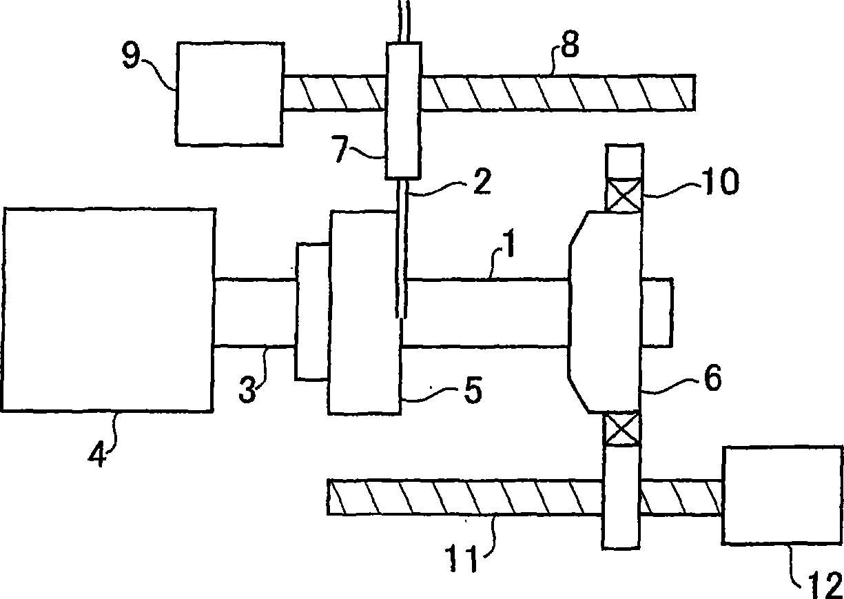
[0042] Hereinafter, the present invention will be described in detail with reference to embodiments of the drawings. figure 1 It is the winding machine of embodiment example. A winding machine having a movable flange 6 is known (for example, refer to JP-A-58-116712). Briefly, here, the wire 2 supplied by the wire supply mechanism 7 is wound on the winding mandrel 1 to form a multi-layer wound air-core coil.

[0043] The wire supply mechanism 7 moves in parallel with respect to the winding mandrel 1 through the feed screw 8 . The feed screw 8 is driven by a motor 9 . The winding mandrel 1 is fixed on the main shaft 3 and driven by the main shaft motor 4 to rotate. A fixed flange 5 and a movable flange 6 are disposed on the winding mandrel 1 . The movable flange 6 is engaged with the feed screw 11 through the bearing 10 . The feed screw 11 is driven by a motor 12 to move the movable flange 6 on the winding mandrel 1 .

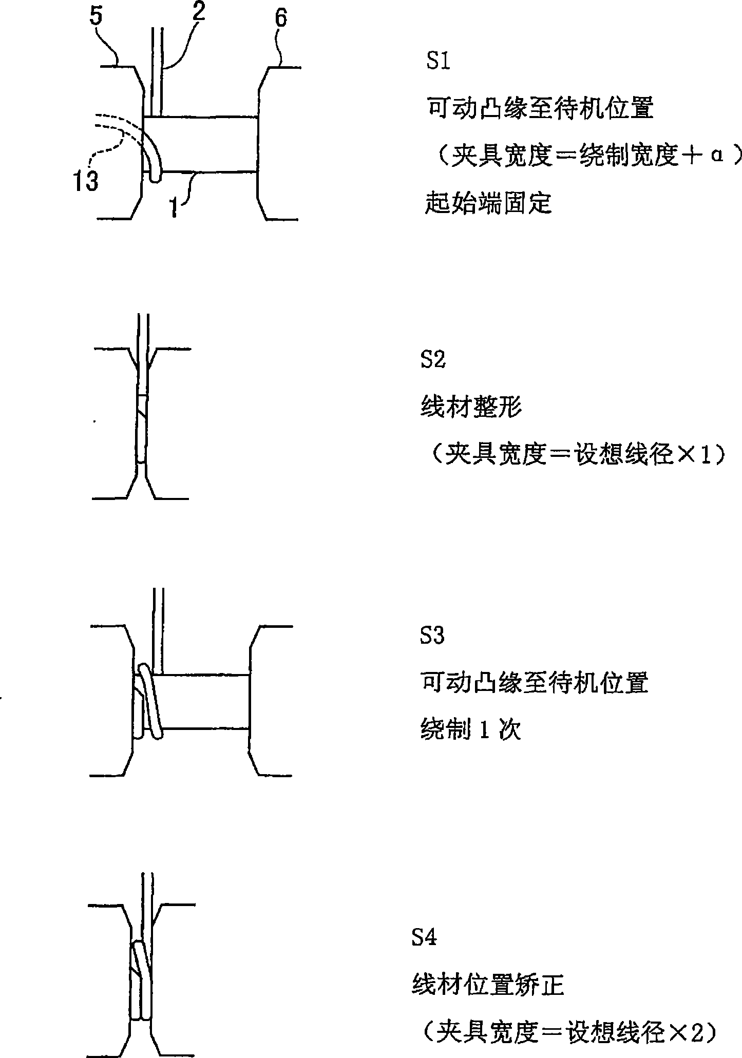
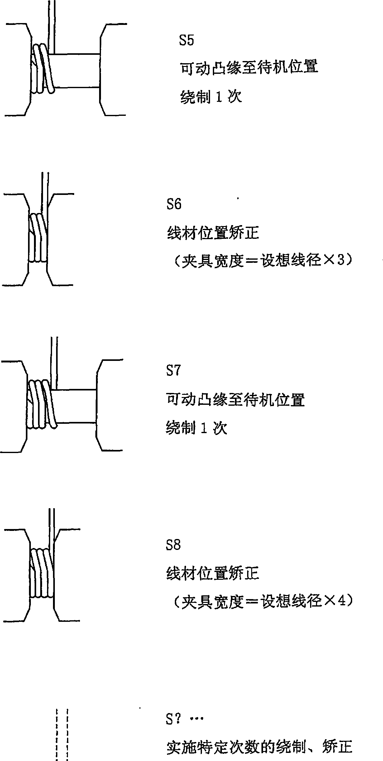
[0044] The winding steps of this winding machine are...


PUM


Abstract

A winding machine hardly causing winding disturbance despite variations in wire diameter. [MEANS FOR SOLVING PROBLEMS] A winding machine provided with a movable flange (6), wherein a wound wire is moved by the movable flange (6), for example, every time the wire is wound and its position is corrected. The winding and the positional correcting are repeated to perform a specified number of windings in a first layer. If the movable flange is moved when winding starts in the first layer, the curved winding start portion of the wire is linearized. If the above specified number of windings is one, winding arrangement is the most elaborate.

Description

technical field [0001] The present invention relates to a winding machine, in particular to a winding machine suitable for winding multi-layer coils. Background technique [0002] When making a multi-layer coil, there is a problem of how to accurately wind the first layer of winding. This is because if the first layer of winding is not accurate, it will cause garbled wires. [0003] Regarding this point, in the past, the main focus was on how to make the windings more compact, and various winding methods and devices have been proposed. [0004] For example, in the invention of Patent Document 1, after the first-layer winding is completed, the movable-side guideway B is moved to the fixed-side guideway A to press the entire first-layer winding and compact each winding. [0005] At this time, the reaction force of the wire to the wire groove B is also detected as required, and the movement of the wire groove B is stopped when the reaction force reaches a certain value, so as...

Claims


Application Information

Patent Timeline
IPC IPC(8): H01F41/06B65H54/10B65H54/28
CPCH01F41/0687B65H54/2848H01F41/0633H01F41/082H01F41/098
Inventor 大野冨士夫高峯一成新井正则
Owner NIPPON SERBIG
Why Eureka
Try Eureka