Transmission structure for conveyer belt for screen decorating machine

A technology of screen printing machine and transmission structure, which is applied in the direction of screen printing machine, printing machine, conveyor, etc., and can solve the problems of short pause of the conveyor belt, poor stability, and difficulty in achieving complete synchronization of the cylinder.

Inactive Publication Date: 2009-04-08
陆新田
View PDF0 Cites 8 Cited by
  • Summary
  • Abstract
  • Description
  • Claims
  • Application Information

AI Technical Summary

Problems solved by technology

Since at least two variable frequency motors are required to be driven alternately and the cylinder moves up and down to pull the conveyor belt 1, it is difficult to achieve c

Method used


Image

  • Transmission structure for conveyer belt for screen decorating machine
  • Transmission structure for conveyer belt for screen decorating machine
  • Transmission structure for conveyer belt for screen decorating machine

Examples


Embodiment Construction

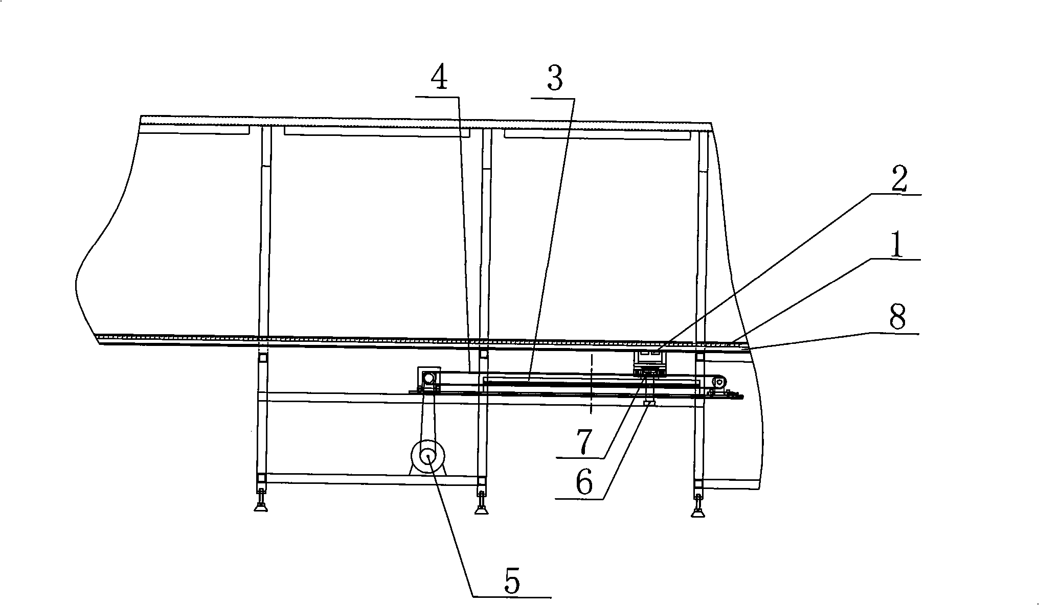
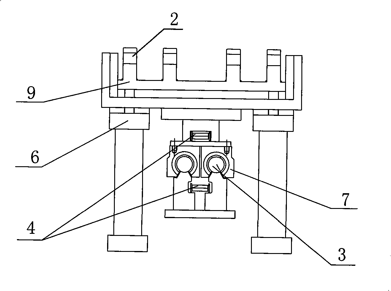
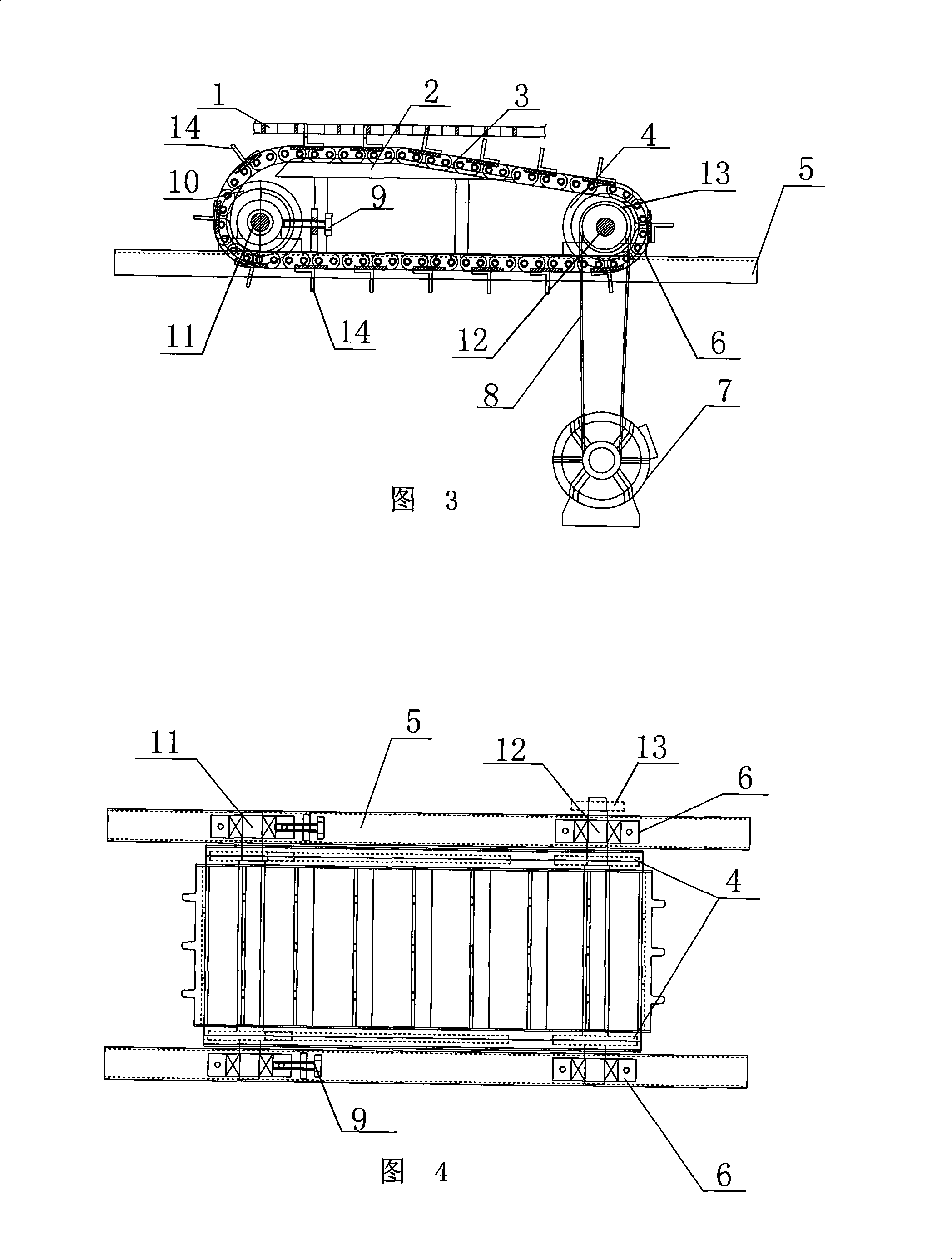
[0011] See Fig. 3, Fig. 4, the present invention comprises conveyer belt 1, conveyer chain 3 and its driving structure, conveyer chain 3 engages with conveyer belt 1 through its externally connected clip 14, and the position of conveyer chain 3 meshes with conveyer belt 1 The two outer parts are respectively obtuse-angled and arc-shaped. This is convenient for the clip 14 to disengage from the conveyor belt 1 after passing the meshing area, and the clip 14 is installed on the adjacent chain links of the conveyor chain 3 respectively; the drive structure includes a motor 7, and the motor 7 is connected to the driving shaft by a chain 8 and a sprocket 13 12. The driving shaft 12 is set with the driving sprocket 4, and the conveying chain 3 is set on the outside of the driving sprocket 4 and the driven sprocket 10. The driving sprocket 4 and the driven sprocket 10 are installed on the bearing housing 6 and the bearing housing 6 respectively. They are respectively installed on the...


PUM


Abstract

The invention relates to a transmission structure for a conveyer belt for a silk screen printing machine, which has simple structure and continuous transmission, and ensures the stable transmission of the conveyer belt. The transmission structure comprises the conveyer belt, a conveyer chain and a driving structure, and is characterized in that the conveyer chain is meshed with the conveyer belt through a fastener connected with the outside of the conveyer chain, and two outside parts at the meshing part of the conveyer chain and the conveyer belt are in shapes of obtuse arc respectively.

Description

(1) Technical field [0001] The invention relates to a screen printing machine component, in particular to a transmission structure of a conveyor belt for a screen printing machine. (2) Background technology [0002] The conveyor belt of the traditional screen printing machine is straight and long. Since the printing of a complete set of patterns must be equipped with multiple screen frames, the conveyor belt is very long and has high requirements for the factory building. A screen printing machine has been designed in the industry. The conveyor belt structure of the printing machine is long and circular, which occupies a small space and has relatively low requirements for the factory building. It is suitable for large, medium and small enterprises. For the conveying structure matching the conveyor belt, see figure 1 , figure 2 When it works, the frequency conversion motor 5 drives the slider 7 to slide on the guide rail 3 through the conveyor chain 4. At the same time, th...

Claims


Application Information

Patent Timeline
IPC IPC(8): B41F15/08B41F15/16B65G17/08B65G17/40B65G23/02
Inventor 陆新田
Owner 陆新田
Why Eureka
Try Eureka