
Wireless remote control device, bridge device and wireless remote control system

A technology for wireless remote control and bridge equipment, which is applied in signal transmission systems, non-electrical signal transmission systems, components of TV systems, etc.

Inactive Publication Date: 2009-04-08
SHARP KK
View PDF2 Cites 2 Cited by
  • Summary
  • Abstract
  • Description
  • Claims
  • Application Information

AI Technical Summary

Problems solved by technology

However, it can still happen that infrared rays do not reach and thus remote control is not possible
For example, in DVD playback devices, when they are placed inside television shelves (in some cases, inside shelves covered by smoked glass doors) or the like, it can be difficult to achieve operational information transmission using infrared light

Method used


Image

  • Wireless remote control device, bridge device and wireless remote control system
  • Wireless remote control device, bridge device and wireless remote control system
  • Wireless remote control device, bridge device and wireless remote control system

Examples


no. 1 example

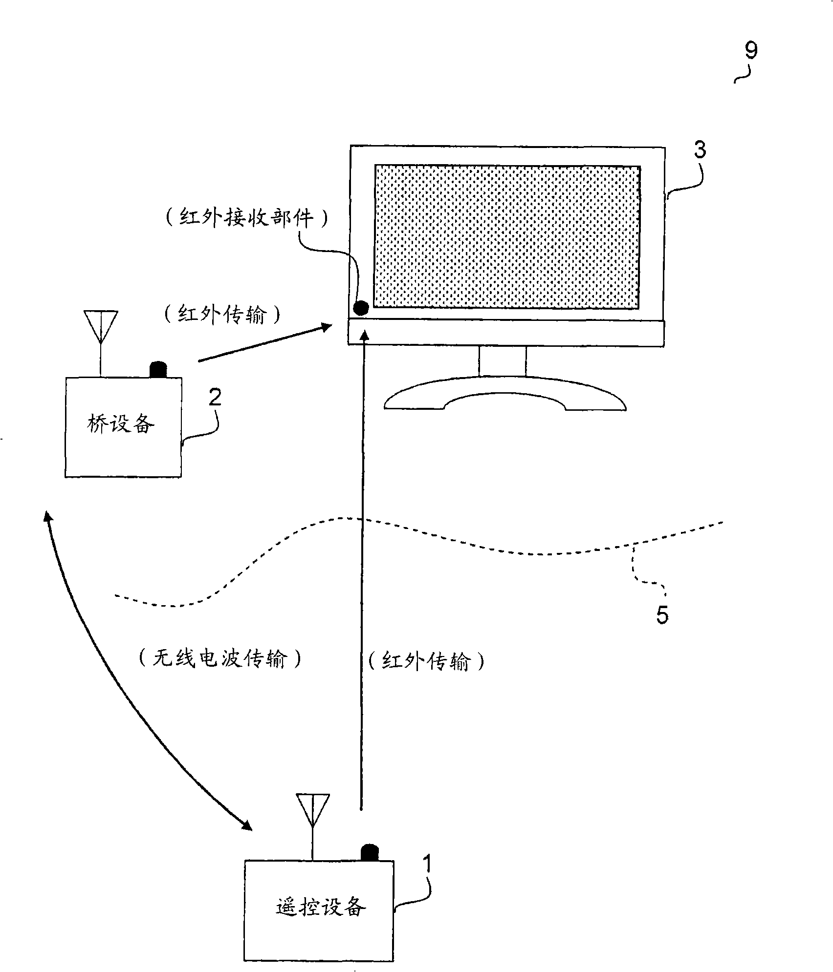
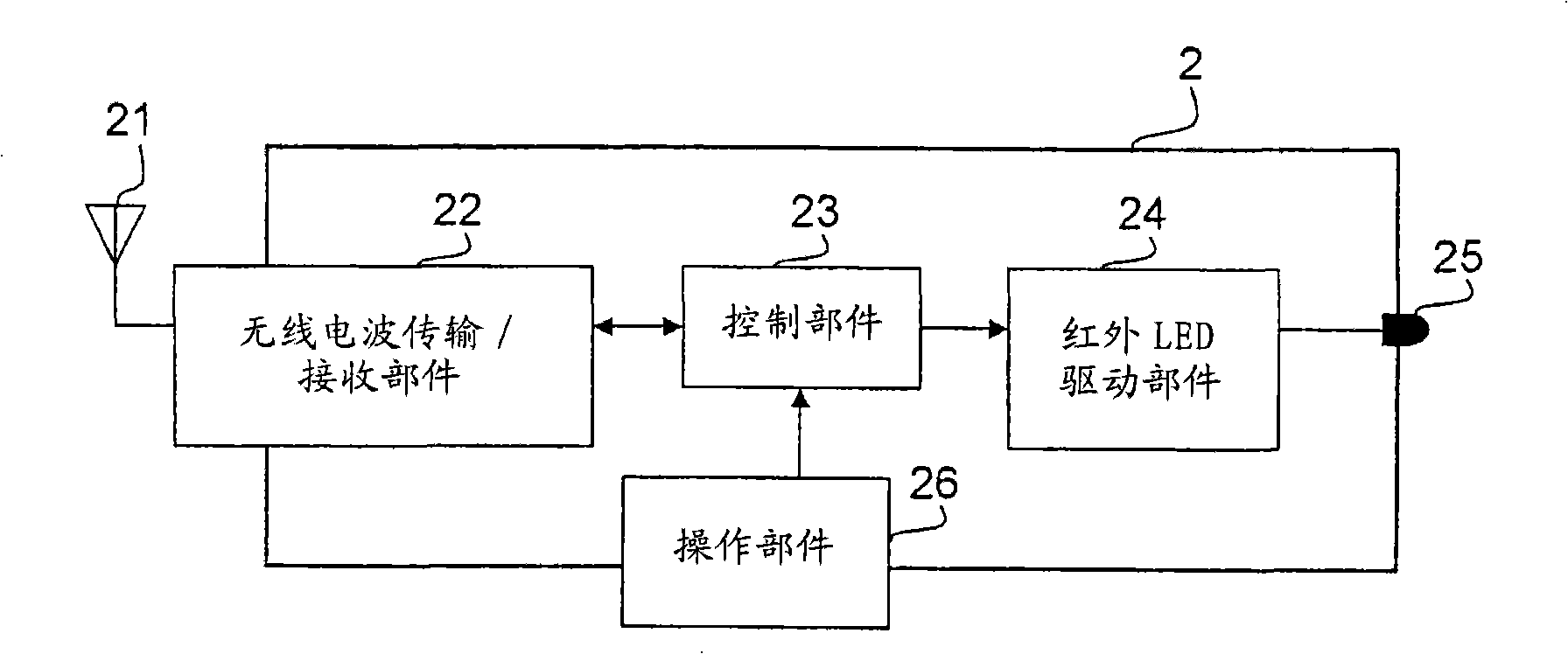
[0037] A television broadcast receiving system as a first embodiment of the present invention will be described below. The configuration of the TV broadcast receiving system is in figure 1 is schematically shown in . As shown in the figure, a television broadcast receiving system 9 has a remote control device 1 , a bridge device 2 and a television broadcast receiver 3 .

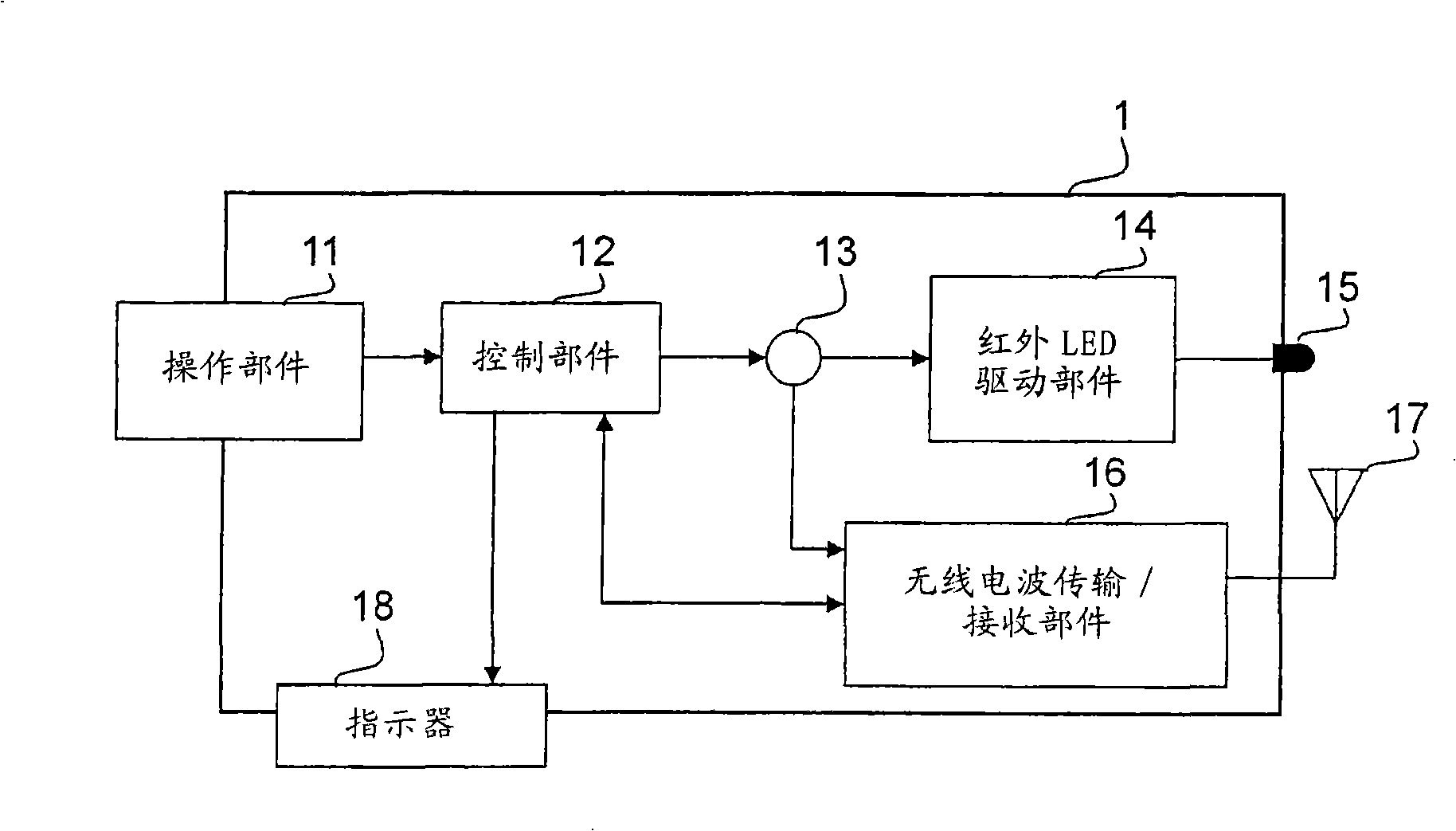
[0038] Such as figure 2 As shown, the remote control device 1 includes: an operation part 11 , a control part 12 , a switch 13 , an infrared LED drive part 14 , an infrared LED 15 , a radio wave transmission / reception part 16 , an antenna 17 and an indicator 18 .

[0039] The operation part 11 is configured as a user interface provided with button switches and other controls. A signal (operation signal) corresponding to the operation performed here is fed to the control section 12 . Thus, the user can input operation information of the television broadcast receiver 3 (for example, information on operatio...

no. 2 example

[0071] Also, a television broadcast receiving system as a second embodiment of the present invention will be described below. Figure 5 The configuration of the television broadcast receiving system is schematically shown in . As shown in the figure, a television broadcast receiving system 9 has a remote control device 1 and a television broadcast receiver 3 . In this embodiment, since the configuration of the remote control device 1, details of operation information, etc. are the same as those of the remote control device 1 in the first embodiment, description thereof will not be repeated.

[0072] The bridge device 4 of the present embodiment is incorporated into the television broadcast receiver 3 as a component (module) therein. Image 6 The configuration of the bridge device 4 is shown in . As shown in the figure, the bridge device 4 includes an antenna 41 , a radio wave receiving section 42 , a control section 43 and an output terminal 44 .

[0073] The radio wave rec...


PUM


Abstract

Disclosed are a wireless remote control device, a bridge device and a wireless remote control system. A wireless remote control device of the present invention includes not only an infrared-transmitting section that transmits operational information to the outside so as to remotely control a predetermined electronic device but also a radio-wave-transmitting section that transmits information to the outside through the use of radio waves as a medium. Thus, it is easily possible to remotely control an electronic device such as audio-visual equipment and to transmit operational information in the form of radio waves with a higher degree of accuracy.

Description

technical field [0001] The present invention relates to a wireless remote control device for remote control of an electronic device such as an audiovisual device, a bridge device for such a wireless remote control device, and a wireless remote control system incorporating these devices. Background technique [0002] In general, wireless remote control devices (hereinafter also simply referred to as "remote control devices") for remotely controlling electronic devices such as audio-visual devices are widely used. In these remote control devices, infrared rays or the like are widely used as a medium through which operation information is transmitted to electronic devices. Documents of conventional techniques related to these devices include JP-A-2002-247667 and JP-A-2000-152347. [0003] However, with the remote control device mentioned above, since infrared rays have a higher degree of linear propagation than other radio waves, when there is an obstacle between the remote co...

Claims


Application Information

Patent Timeline
Patent Type & Authority Applications(China)
IPC IPC(8): G08C23/04H04N5/44H04N5/00H04Q9/00
CPCG08C2201/63G08C2201/40G08C23/04G08C17/02
Inventor 田口耕一
Owner SHARP KK
Learn More