Circuit device, circuit module and outdoor unit
A technology of circuit devices and circuit modules, which is applied in the direction of circuits, electrical components, electric solid devices, etc., and can solve problems such as wrong actions
- Summary
- Abstract
- Description
- Claims
- Application Information
AI Technical Summary
Problems solved by technology
Method used
Image
Examples
no. 1 Embodiment
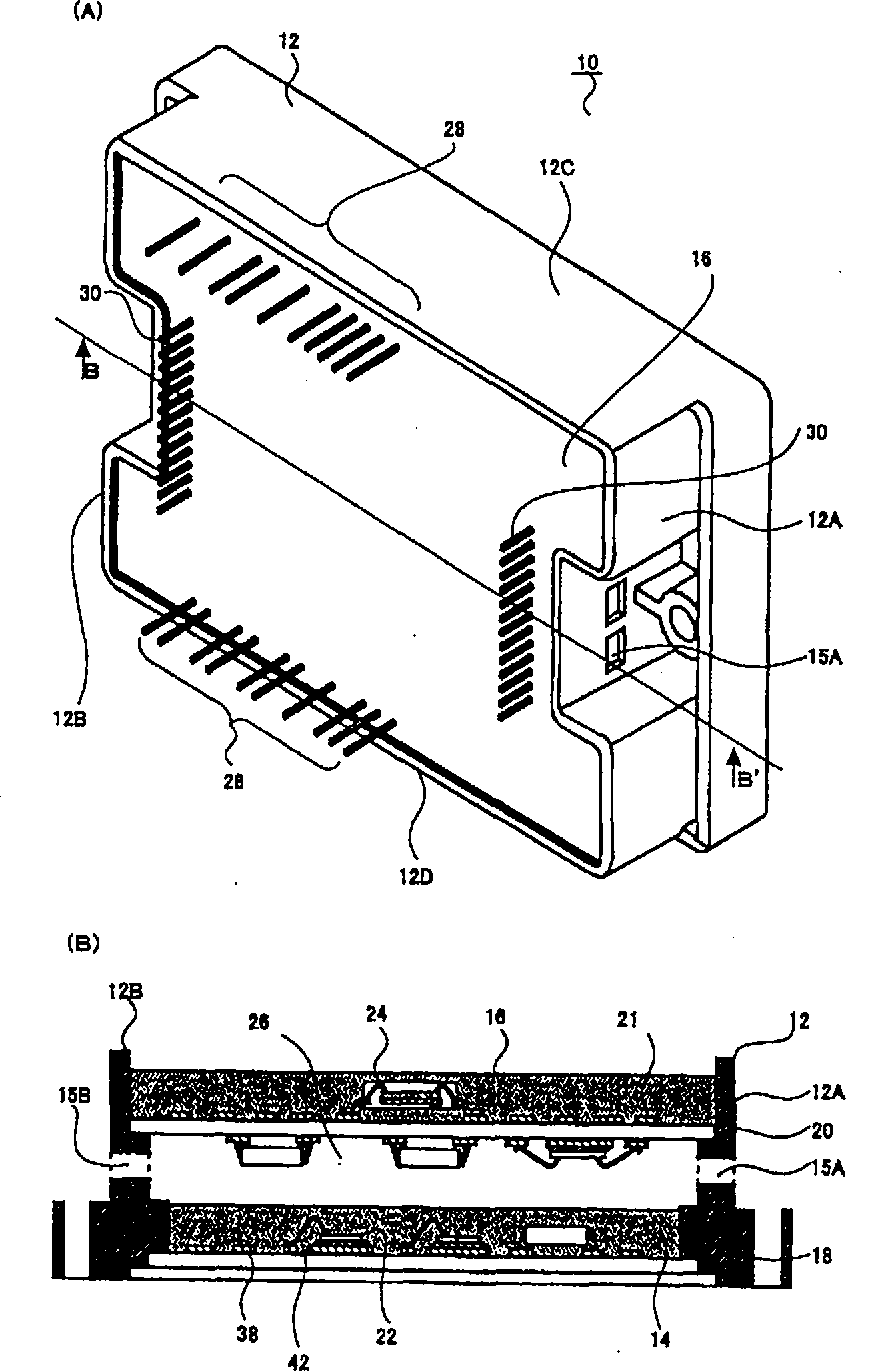
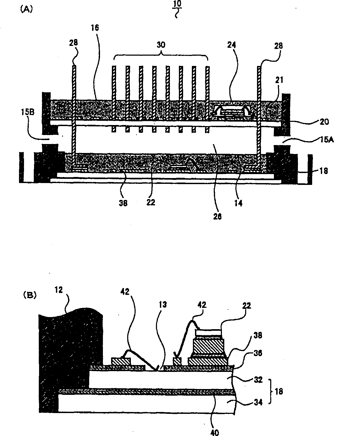
[0077] The following reference figure 1 The configuration of the hybrid integrated circuit device 10 as an embodiment of the circuit device will be described. figure 1 (A) is a perspective view of the hybrid integrated circuit device 10, figure 1 (B) is figure 1 (A) A sectional view taken along the line B-B'.
[0078] reference figure 1 (A) and figure 1 (B) In the hybrid integrated circuit device 10, the first circuit board 18 and the second circuit board 20 are overlapped and assembled on the cover material 12. A first circuit element 22 (for example, a power transistor) is arranged on the upper surface of the first circuit board 18, and a second circuit element (for example, a microcomputer) is arranged on the upper surface of the second circuit board 20. Furthermore, a hollow portion 26 (internal space) not filled with sealing resin is provided inside the outer cover material 12, and the hollow portion 26 and the outside are configured to pass through a communication port...
no. 2 Embodiment
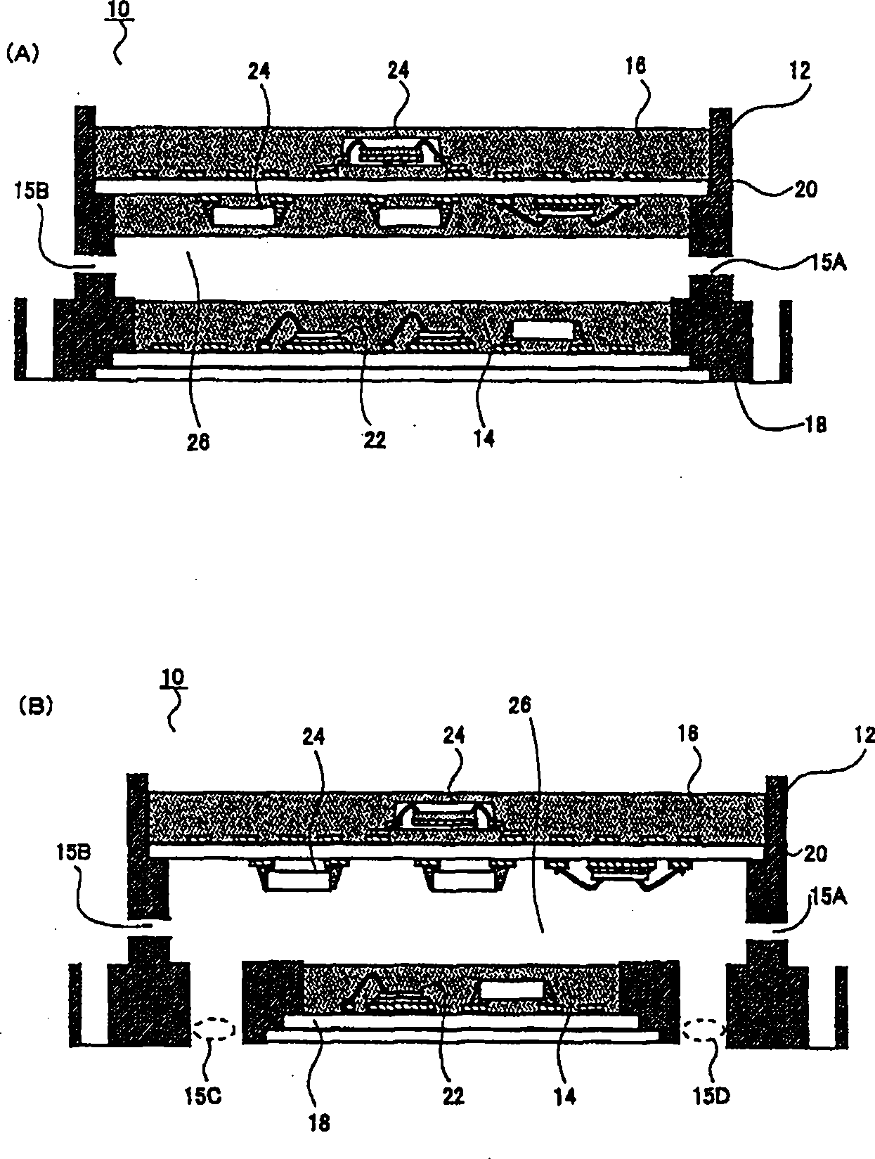
[0129] The following reference Image 6 and Figure 7 The second embodiment will be described. The basic content of this embodiment is the same as that of the above-mentioned first embodiment, with the difference being the structure of the opening 19 that communicates the inside and outside of the device.
[0130] reference Image 6 Next, the configuration of the hybrid integrated circuit device 10 of this embodiment will be described. Image 6 (A) is a perspective view showing the hybrid integrated circuit device 10, Image 6 (B) is Image 6 (A) A sectional view taken along the line B-B'.
[0131] reference Image 6 (A) At the corners of the outer cover 12, four openings 19 for communicating the hollow portion 26 of the outer cover 12 with the outside are provided. The opening 19 has a square shape in plan view, and is formed by protruding the side wall of the outer cover material 12 to the outside.
[0132] By ventilating the air in the hollow portion 26 of the outer cover 12 thro...
no. 3 Embodiment
[0143] reference Figure 8 to Figure 13 , Describe the structure of the circuit module of this embodiment.
[0144] reference Picture 8 (A) In this embodiment, two metal substrates are used. The lower metal substrate 201B is a base substrate, and is formed so that the entire circumference of the upper metal substrate 201A is larger by L2. This distance L2 is called the extension surface distance, and is used to improve the withstand voltage characteristics between the first substrate 201A and the back surface of the base substrate 201B when the circuit module is actually constructed.
[0145] First, the outer cover 203 will be described. In addition, the cover material 203 is in the shape of a square column with the center removed. That is, there are four side walls, and the four side walls of 203A, 203B, and 203C and 203D on the left and right sides are formed integrally with respect to the paper surface. Therefore, there are openings 220 and 221 below and above. In addition,...
PUM
 Abstract
Description
Claims
Application Information
 - R&D Engineer
- R&D Manager
- IP Professional
- Industry Leading Data Capabilities
- Powerful AI technology
- Patent DNA Extraction
Browse by: Latest US Patents, China's latest patents, Technical Efficacy Thesaurus, Application Domain, Technology Topic, Popular Technical Reports.
© 2024 PatSnap. All rights reserved.Legal|Privacy policy|Modern Slavery Act Transparency Statement|Sitemap|About US| Contact US: help@patsnap.com


