
Data output device, equipment control device, and multimedia delivery system

An output device, multimedia data technology, applied in the direction of two-way working system, etc., can solve the problems of not being able to continue to start audio-visual, not considering data transmission, not being able to use the memory client to interrupt the position, etc.

Inactive Publication Date: 2009-04-08
PANASONIC CORP
View PDF0 Cites 10 Cited by
  • Summary
  • Abstract
  • Description
  • Claims
  • Application Information

AI Technical Summary

Problems solved by technology

[0007] However, RTSP is aimed at one-to-one communication between the server and the client, and does not consider the data transmission to other clients, so the above-mentioned change of the room and the continuation of viewing cannot be realized.
Also, since the client has changed, it is not possible to take advantage of the method of remembering the location of the client interruption

Method used


Image

  • Data output device, equipment control device, and multimedia delivery system
  • Data output device, equipment control device, and multimedia delivery system
  • Data output device, equipment control device, and multimedia delivery system

Examples


Embodiment 1

[0147] Embodiments of the present invention will be described below with reference to the drawings.

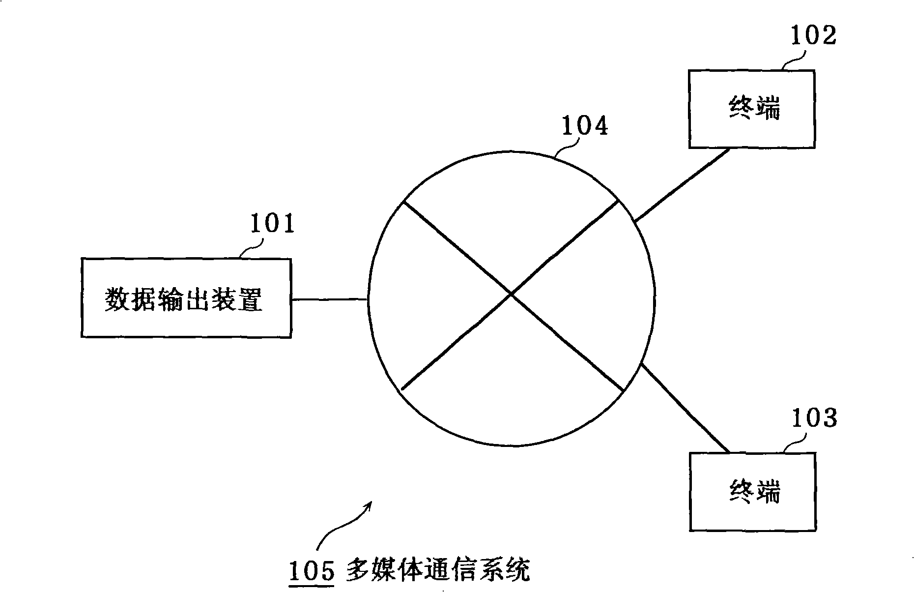
[0148] figure 1 It is a structural diagram of the multimedia communication system in Embodiment 1 of the present invention.

[0149] figure 1 The shown multimedia communication system 105 includes: a data output device 101 , a first terminal 102 , a second terminal 102 , and a network 104 . The data output device 101 , the terminal 102 and the terminal 103 are connected to the network 104 and can communicate with each other through the network 104 .

[0150]In this embodiment, the data output device 101 receives requests from the terminal 102 and the terminal 103 transmitted via the network 104 . And, the stored information, attributes, or multimedia data of each content are transmitted to the terminal 102 and the terminal 103 through the network 104 according to the request.

[0151] When the data output device 101 receives the output of the data being executed by the rec...

Embodiment 2

[0326] Figure 13 This is an example of the configuration of the multimedia communication system in Embodiment 2 of the present invention.

[0327] like Figure 13 As shown, the multimedia communication system 1305 includes: a data output device 1301 , a first terminal 1302 , a second terminal 1303 , and a network 1304 . The data output device 1301 , the terminal 1302 and the terminal 1303 are connected to the network 1304 and communicate with each other through the network 1304 .

[0328] The data output device 1301 in this embodiment includes a network interface and a storage unit for storing multimedia data, and is a CATVSTB (Set Top Box) that receives data broadcasting.

[0329] The data output device 1301 stores the received multimedia data of the data broadcast content in the storage unit. And, it is connected to the network 1304 through a network interface. And, a request from the terminal 1302 and the terminal 1303 transmitted via the network 1304 is received. The...


PUM


Abstract

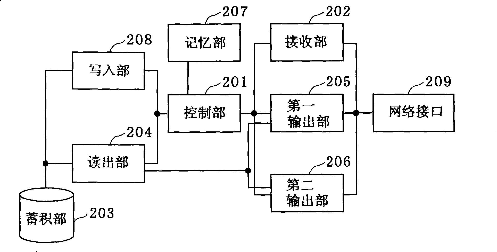
The invention provides a technology which can appropriately resume reproduction of paused content from a terminal in another terminal in a multimedia delivery system made up of a multimedia content server and plural terminals connected to a network. A data output device outputs multimedia data that includes at least one of video and audio, the data output device includes a control unit operable to generate resume position information and to cause said storage unit to store the generated resume position information when a pause request, which is a request to pause output by a first or a second output unit, is received by a receiving unit which receives a signal from an external device, and to read out the resume position information from the storage unit, to cause the readout unit to read out the multimedia data, starting from a resume position shown by the resume position information, from the accumulation unit and to cause the first or the second output unit to output the read-put multimedia data to the output destination.

Description

technical field [0001] The present invention relates to the output and control of multimedia digital content to a network or the like. Background technique [0002] In recent years, digital broadcasting such as BS digital broadcasting, CS110-degree digital broadcasting, and terrestrial digital broadcasting have started. Furthermore, HDD recorders, DVD (Digital Versatile Disc) recorders, and the like are becoming popular. Accordingly, the number of digitized multimedia contents that can be used at home increases. [0003] And, on the other hand, since the broadband environment is maintained, access to the Internet from home is also widespread. Along with these developments, the so-called home network that connects various rooms in a home with an IP network is gradually becoming popular. [0004] In this situation, the digital broadcast received by the digital broadcast receiver in the home or the digital content stored in the recorder can be viewed and listened to in anoth...

Claims


Application Information

Patent Timeline
Patent Type & Authority Applications(China)
IPC IPC(8): H04N7/173
Inventor 宗续敏彦
Owner PANASONIC CORP
Learn More