
Dish washer/dryer

A tableware washing and drying machine technology, which is applied to the parts of the tableware washing machine/rinsing and washing machine, etc., can solve the problems that the air volume cannot be discharged for cooling, and cannot eliminate the hot air feeling, etc., and achieves the effect of improving drying performance and reducing temperature and humidity.

Active Publication Date: 2009-04-15
PANASONIC CORP
View PDF1 Cites 6 Cited by
  • Summary
  • Abstract
  • Description
  • Claims
  • Application Information

AI Technical Summary

Problems solved by technology

That is, since the fresh outside air is mixed with the exhaust gas of the cleaning tank in the form of a secondary air flow by the fluid force of the high-temperature and high-humidity main air flow flowing into the exhaust port, although the high-temperature and high-humidity cleaning tank discharge can be reduced The temperature of the air, but the air volume of the fresh outside air cannot sufficiently cool the exhaust air flow, and cannot eliminate its hot wind feeling

Method used


Image

  • Dish washer/dryer
  • Dish washer/dryer
  • Dish washer/dryer

Examples


Embodiment approach 1

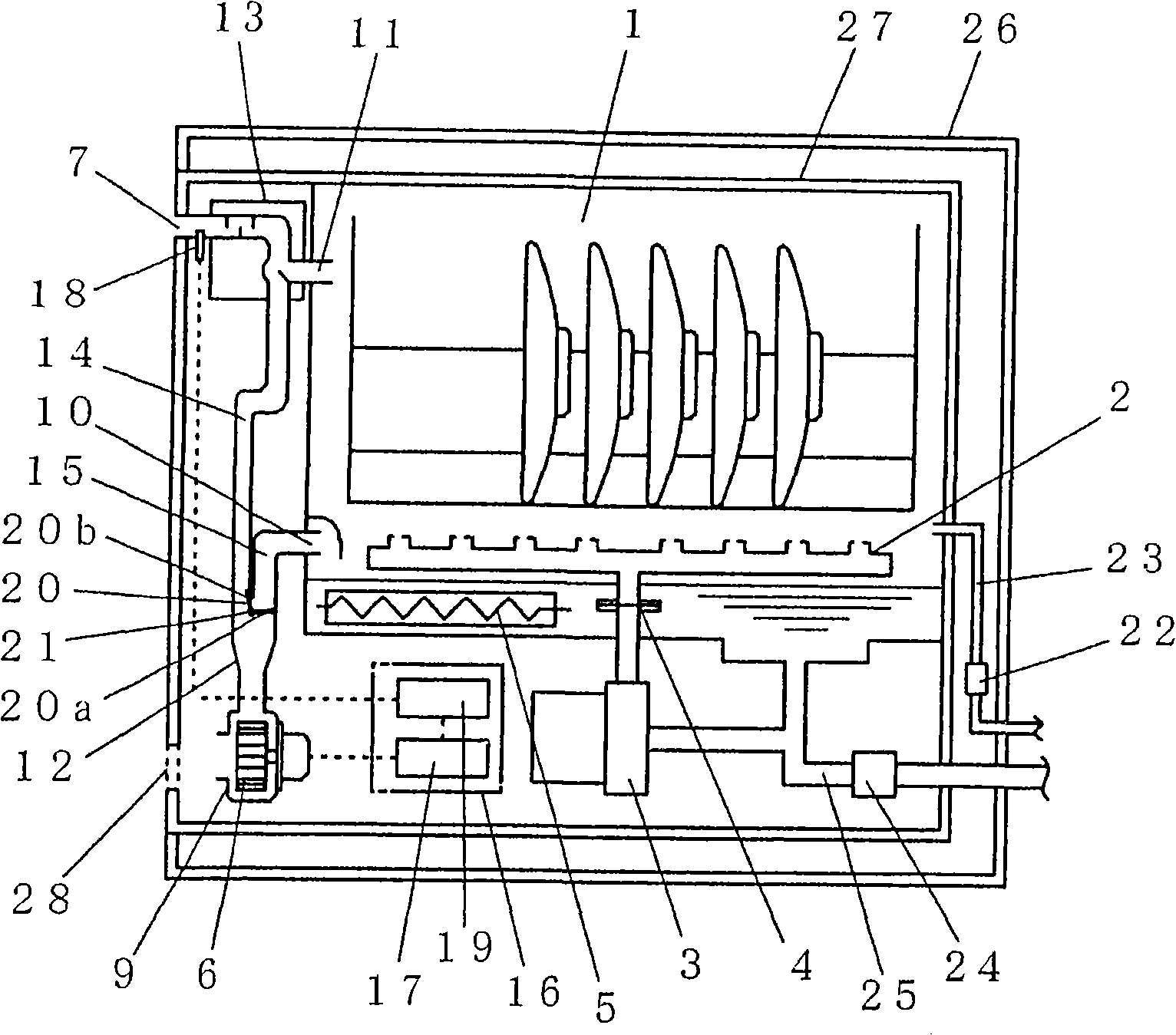
[0040] figure 1 It is a structural cross-sectional view of the dish washer and dryer according to the first embodiment of the present invention.

[0041] Such as figure 1 As shown in , the tableware washing and drying machine of this embodiment is provided with a washing tank 1 for accommodating tableware and other objects to be cleaned. Below the washing tank 1, a washing device 4 and a heating device 5 for heating the washing water to increase its temperature are provided. . The cleaning device 4 is provided with a cleaning nozzle 2 for spraying cleaning water onto the object to be cleaned and circulating the cleaning water, and a cleaning pump 3 for pressurizing the cleaning water. In addition, the dish washing and drying machine of the present embodiment is also provided with a drying device 9 for discharging the moisture in the washing tank 1 to make the inside of the washing tank 1 dry. A blower 6 which is referred to as "outside air" for short, and an exhaust port ...

Embodiment approach 2

[0089] Figure 7 It is a schematic diagram of the damper structure in the second embodiment of the present invention.

[0090] Figure 7 neutralize Figure 1 to Figure 6 The same components or the same functional blocks in the illustrated embodiment 1 are marked with the same symbols, their repeated descriptions are omitted, and only the differences are focused on for description.

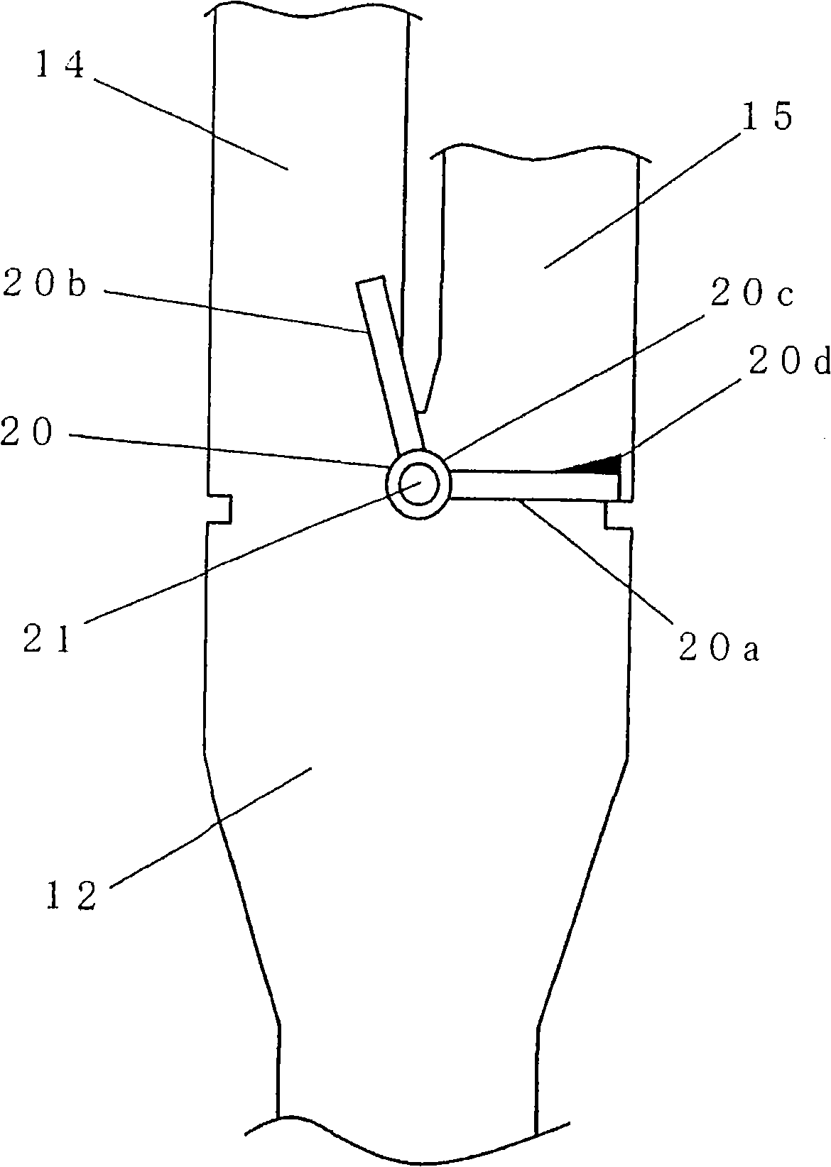
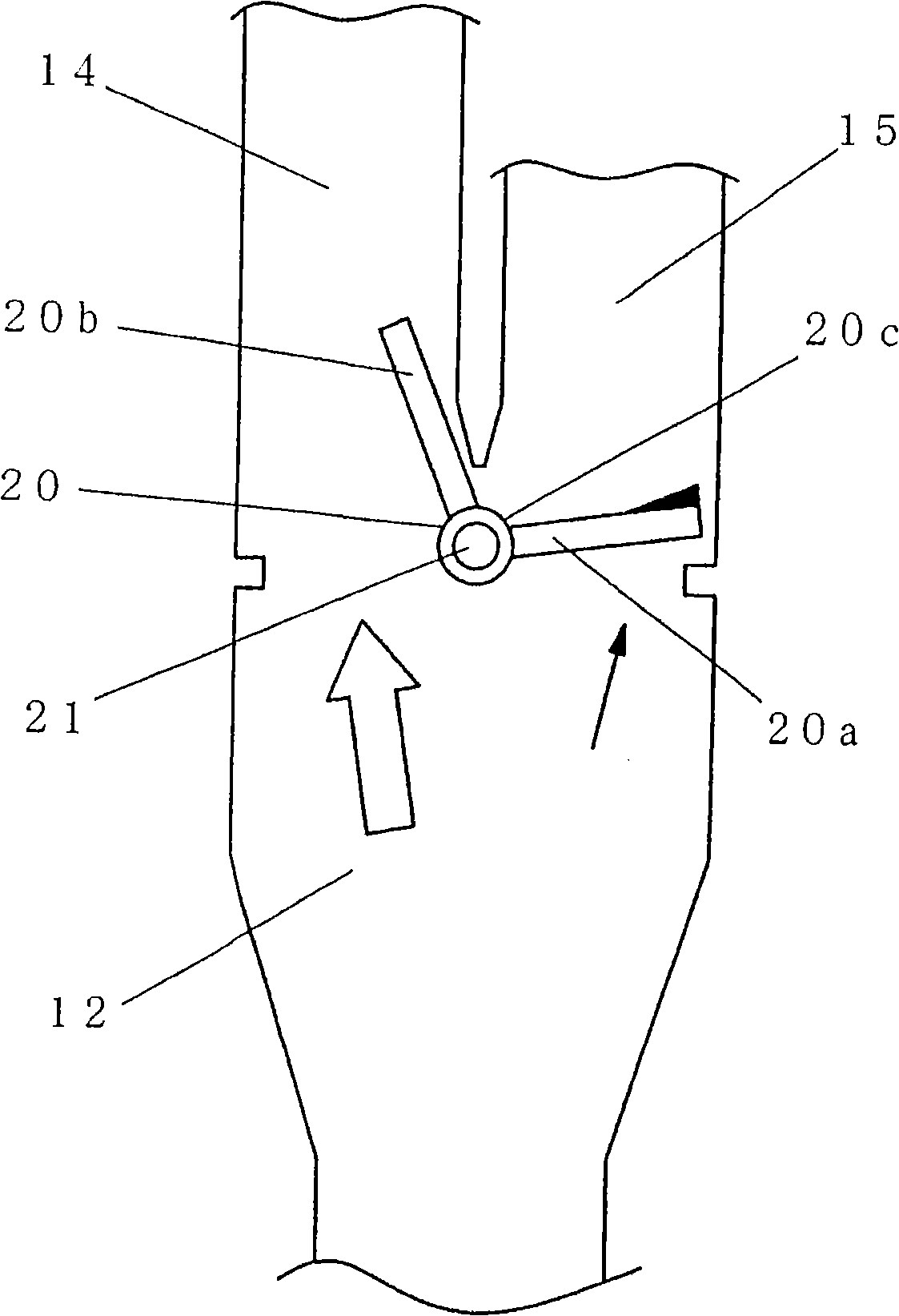
[0091] Figure 7The damper 20 shown in is provided with a posture setting device 32 that can change the coupling posture of the cleaning tank damper 20a and the external air damper 20b, so that the coupling angle α between the cleaning tank damper 20a and the external air damper 20b can be changed. , the relative position between each other can change.

[0092] In order to change the coupling posture according to the temperature of the washing tank 1, the posture setting device 32 uses a shape memory body 33 whose shape can be changed according to the temperature. The support shaft 21 of the d...


PUM


Abstract

The invention provides a dish washer / dryer, which mixes enough outside-air in exhaust air of a rinse tank, reduces temperature and water of the exhaust air, increases comfort of the exhaust air when in drying operation. The dish washer / dryer comprises a mixing section (13) for mixing the outside-air with washing-tub-inside-air, and an air volume distribution section (12) for changing the feeding ratio of outside-air into the washing tub and the mixing section. The air volume distribution section is provided with an air door (20) causing opening to be changed through air pressure in an inside-air channel (15) of the rinse tank and an outside-air channel, a rinse tank air door (20a) arranged on the inside-air channel of the rinse tank and an outside-air door (20b) arranged on the outside-air channel are integrated. In the drying operation, the ratio of the outside-air flowing into the mixing section and the air in the rinse tank can be freely distributed / given, thereby reducing temperature and humidity of the exhaust air, reliably preventing hot air feel and increasing drying performance.

Description

technical field [0001] The invention relates to a tableware washing and drying machine for accommodating, automatically washing and drying the objects to be cleaned, which is arranged in a kitchen or the like. Background technique [0002] In the existing tableware washing and drying machine of this kind, in order to make the object to be cleaned dry after the washing is completed, the structure of blowing outside air into the washing tank to discharge the high-temperature and humid air in the washing tank is adopted (one example of which is Reference may be made to Japanese Patent Laid-Open Publication No. 2000-166847). [0003] Figure 10 Shown in the above-mentioned reference 1 in the existing dish washer and dryer. Such as Figure 10 As shown in , this existing tableware washing and drying machine is provided with: a cleaning tank 1 for loading the objects to be cleaned; a cleaning nozzle 2 for spraying cleaning water and a cleaning pump 3 for pressurizing the cleaning ...

Claims


Application Information

Patent Timeline
IPC IPC(8): A47L15/42A47L15/46A47L15/48
Inventor 岩永茂稻田刚士石川启治的场识义
Owner PANASONIC CORP
Learn More