Medical atomising device

A technology of atomization device and cone sleeve, which is applied in the direction of atomizer for treatment, etc., can solve the problems of ineffective resistance, large accumulation tolerance, affecting atomization effect, etc.

Inactive Publication Date: 2009-04-15
HSINER
View PDF6 Cites 5 Cited by
  • Summary
  • Abstract
  • Description
  • Claims
  • Application Information

AI Technical Summary

Problems solved by technology

[0004] 1. Since the atomizing device is assembled from three components including the container 1, the atomizing nozzle 2 and the upper cover 3, it often leads to a relatively large cumulative assembly tolerance. Therefore, once the cumulative tolerance is too large, the The stop wall 303 of the upper cover 3 may not be able to effectively resist the impact plate 203 of the atomizing nozzle 2, causing the atomizing nozzle 2 to move relative to the tapered portion 101 during the atomization process, causing the atomizing nozzle to 2 and the distance between the tapered part 101 changes, which affects the atomization effect
[0005] 2. The container 1, atomizing nozzle 2 and upper cover 3 of the atomizing device are three independent components, all of which need to be manufactured separately, thus increasing the manufacturing cost of the atomizing device
[0007] It can be seen that the above-mentioned existing medical atomization device obviously still has inconvenience and defects in structure and use, and needs to be further improved urgently.
In order to solve the above-mentioned problems, the relevant manufacturers have tried their best to find a solution, but no suitable design has been developed for a long time, and the general products do not have a suitable structure to solve the above-mentioned problems. This is obviously related. The problem that the industry is eager to solve

Method used


Image

  • Medical atomising device
  • Medical atomising device
  • Medical atomising device

Examples


Embodiment Construction

[0026] In order to further explain the technical means and effects of the present invention to achieve the intended purpose of the invention, the specific implementation, structure, characteristics and effects of the medical atomization device proposed according to the present invention will be described below in conjunction with the accompanying drawings and preferred embodiments. , as detailed below.

[0027] The aforementioned and other technical contents, features and effects of the present invention will be clearly presented in the following detailed description of a preferred embodiment with reference to the drawings.

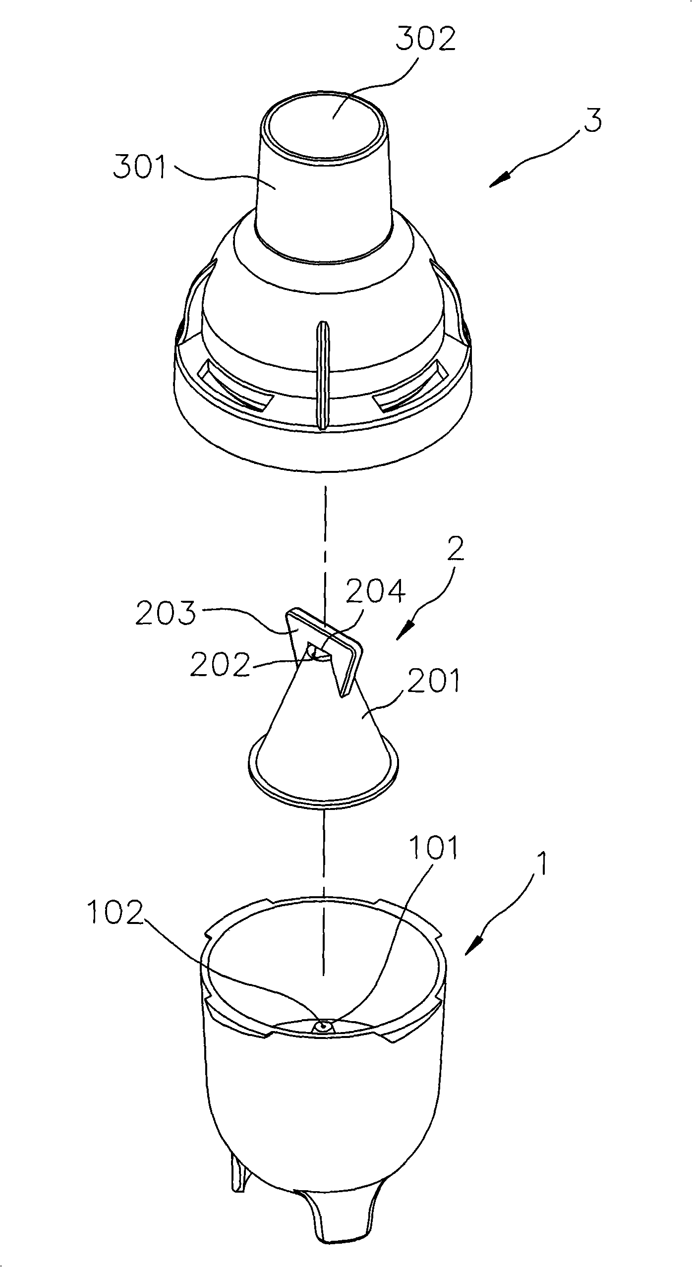
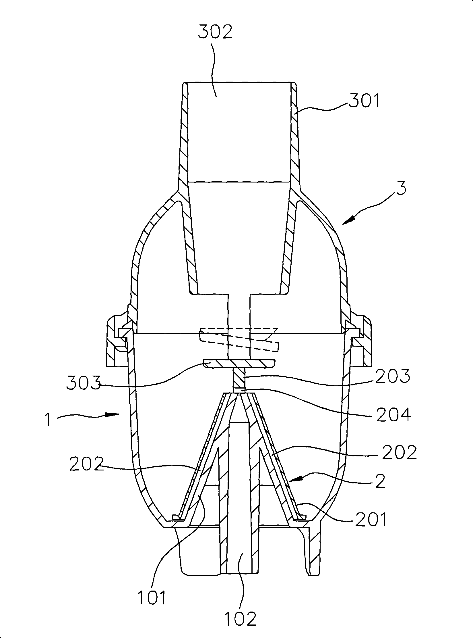
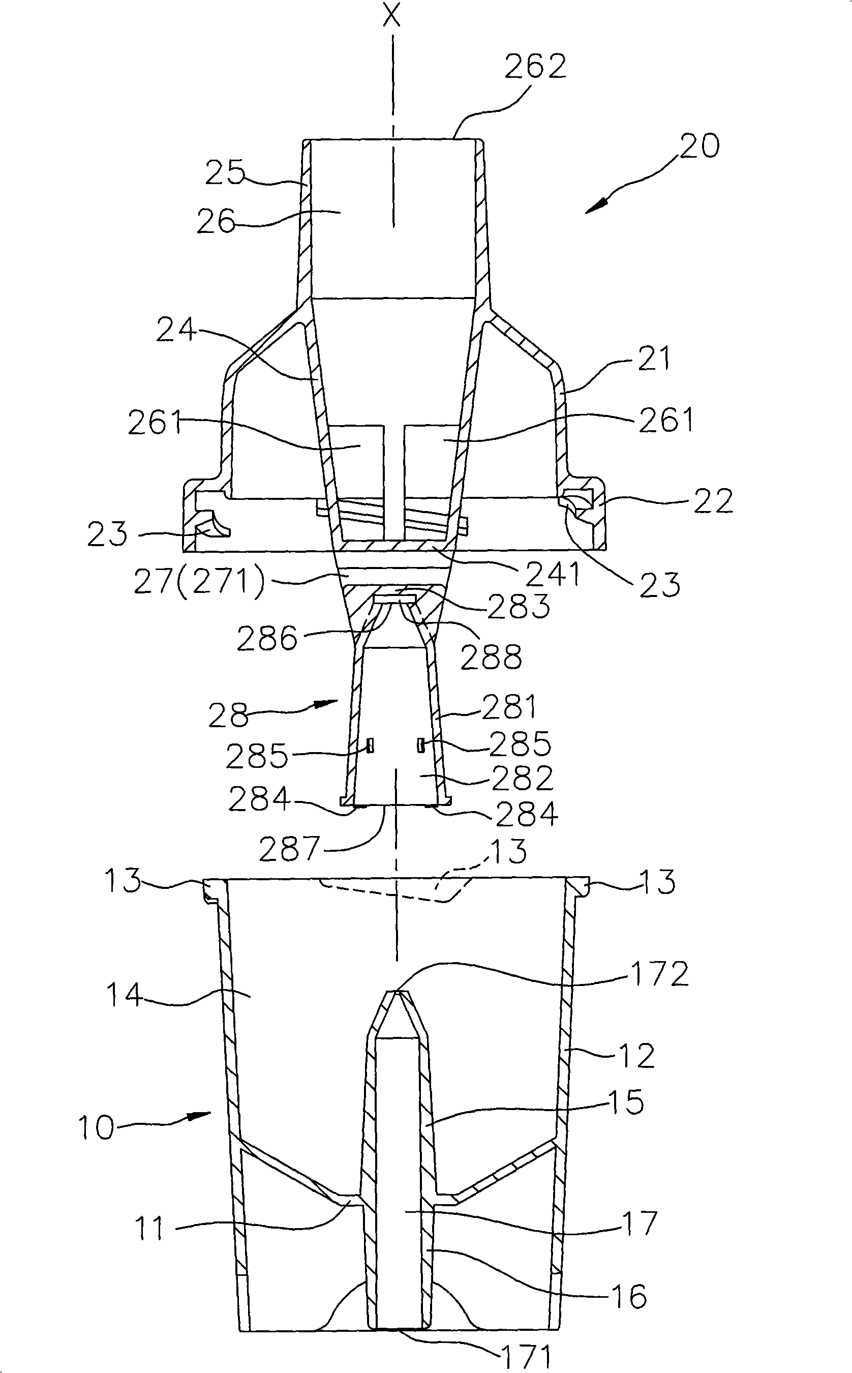
[0028] see image 3 , Figure 4 and Figure 5 as shown, image 3 It is an exploded schematic view of a preferred embodiment of the medical atomization device of the present invention, Figure 4 It is an exploded cross-sectional schematic diagram of another angle, illustrating that one upper cover of the preferred embodiment is rotated to another angle...


PUM


Abstract

The invention relates to a medical atomization device, which comprises a container and an upper cover, wherein the container is provided with a bottom wall, an enclosing wall, a chamber, a conical part which is extended upwards from the bottom wall, an air inlet part which is extended downwards from the bottom wall, and an air inlet channel which runs through the conical part and the air inlet part; the upper cover is provided with a circumferential wall, a joining annular wall, an inner tube part which is extended downwards from the circumferential wall, an outer tube part which is extended upwards from the circumferential wall, an exhaust passage which is extended into the inner tube part and the outer tube part, and a conical sleeve part which is connected with the inner tube part and extended downwards from the inner tube part; and the conical sleeve part is provided with a sleeved hole. When the upper cover is combined with the container, the conical part is sleeved into the sleeved hole; an annular gap is formed between the conical sleeve part and the conical part; and a bottom gap which is communicated with the annular gap is formed between the bottom end of the conical sleeve part and the top surface of the bottom wall. The medical atomization device makes the bottom gap and the annular gap always maintain scheduled size and width in virtue of the combination of the upper cover and the container, not only can reduce the accumulated assembly tolerance but also has low manufacturing cost, and can generate good atomization effect.

Description

technical field [0001] The invention relates to a medical liquid atomizing device, in particular to a medical atomizing device which can reduce the cumulative tolerance of assembly, has low manufacturing cost and has good atomizing effect. Background technique [0002] see figure 1 , figure 2 as shown, figure 1 It is an exploded three-dimensional schematic diagram of an existing medical atomization device, figure 2 It is a cross-sectional schematic diagram of its combined structure. The existing medical atomization device comprises a container 1 with a conical portion 101 and an air inlet channel 102, a container 1 with a conical wall 201, and two containers recessed on an inner wall surface of the conical wall 201. The guide channel 202, an impact plate 203 arranged on the top of the conical wall 201 and an atomizing nozzle 2 with a vent hole 204 provided on the impact plate 203, and a pipe portion 301, a row The air channel 302 and the upper cover 3 are arranged on ...

Claims


Application Information

Patent Timeline
Patent Type & Authority Applications(China)
IPC IPC(8): A61M11/00
Inventor 张二郎
Owner HSINER
Why Eureka
Try Eureka