Eureka AIR delivers breakthrough ideas for toughest innovation challenges, trusted by R&D personnel around the world.

Arm for automatic machine

A technology of automatic machinery and arms, which is applied in the direction of manipulators, chucks, manufacturing tools, etc., can solve the problem that the fork arm hits the load placed on the lower layer, and the front end may touch the load, etc.

Inactive Publication Date: 2009-04-15
ESPEC CORP
View PDF1 Cites 2 Cited by
  • Summary
  • Abstract
  • Description
  • Claims
  • Application Information

AI Technical Summary

Problems solved by technology

Furthermore, in the case of taking out a load placed on each level of the storage rack, when the fork arm is inserted under the load, the front end of the fork arm raised upward at a large angle may hit the load, or, for To avoid this situation, when the fork is inserted in a lowered state, the base end of the fork may hit the load placed on the lower layer.
[0009] In order to solve the above problems, it is possible to increase the interval between each shelf of the storage rack, but in this case, the height of the storage rack has to be increased in order to ensure the storage capacity, and with this increase in height, the ceiling of the place where the storage rack is installed must be increased. Other issues such as height or reachable height of handling robots

Method used


Image

  • Arm for automatic machine
  • Arm for automatic machine
  • Arm for automatic machine

Examples


Embodiment Construction

[0045] Embodiments of the present invention will be described below with reference to the drawings.

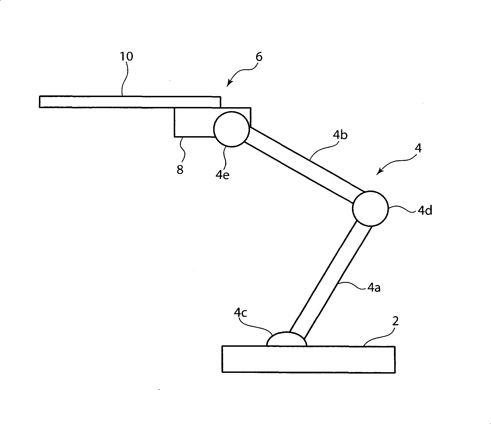
[0046] First, refer to Figure 1 to Figure 8 The structure of the robot arm 6 according to the embodiment of the present invention and a transfer robot including the robot arm 6 will be described.

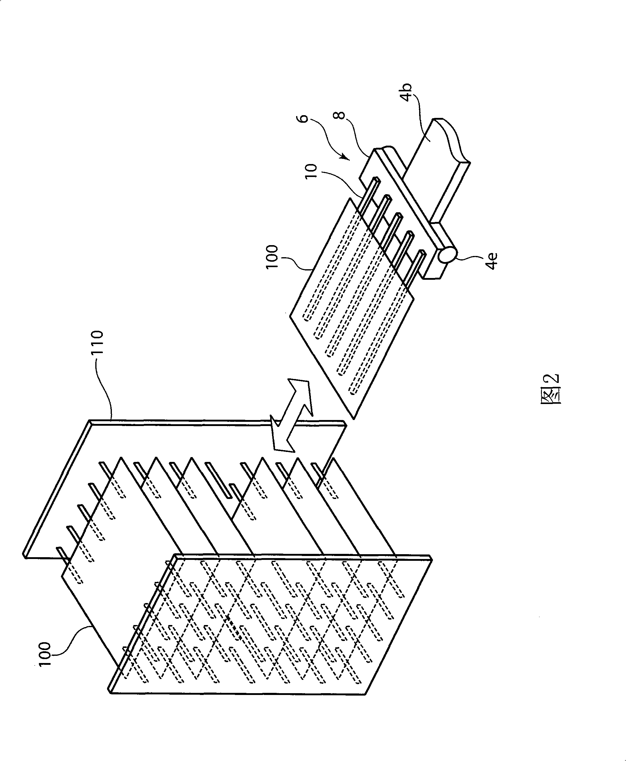
[0047] The robot for conveyance of this embodiment is an apparatus for mounting the glass substrate 100 for liquid crystal displays as a conveyance on the fork (fork, which will be described later) 10 thereof, and conveying the glass substrate 100 . As shown in FIG. 2 , this transfer robot is used to place the glass substrate 100 on each layer of the storage rack 110 or to take out the glass substrate 100 placed on each layer of the storage rack 110 . and, if figure 1 As shown, the transfer robot includes a base part 2, an arm part 4, and an arm 6 for the robot.

[0048] The base portion 2 is a base portion of a conveyance robot, and the arm portion 4 is mounted on the base port...


PUM


Abstract

The present invention provides an arm for automatic machine, including a furcal arm extending in a slope state of more upwards if it is closer to the front end. The furcal arm is used for loading and carrying objects, wherein, the furcal arm is provided with aggravation component which can move at least to a first position and a second position which is closer to the front end than the first position.

Description

technical field [0001] The present invention relates to arms for robotic machines. Background technique [0002] Hitherto, transport robots have been used to transport objects such as glass substrates for liquid crystal displays, and Japanese Patent Laid-Open Publication No. 2006-110662 discloses an example of such a transport robot. [0003] The transfer robot disclosed in the gazette includes an arm for the robot that is equipped with a fork protruding from a mounting position on the arm and that moves two-dimensionally or three-dimensionally. In this transport robot, after inserting the fork arm between the loads placed on the multi-level positions in the storage rack, the fork arm is raised to load the load, and the arm is moved in this state to unload the load. . [0004] In addition, the arm for automatic machinery is provided with a front-end position adjustment device. When the fork arm is long, the fork arm bends due to its own weight and its front end hangs down....

Claims


Application Information

Patent Timeline
IPC IPC(8): B25J17/02
CPCB25J15/0014B25J19/06
Inventor 手钱永充
Owner ESPEC CORP
Why Eureka
Eureka Blog
Learn More