Reverse opening type slide fastener
一种反开式、拉链的技术,应用在滑动扣件元件、应用、扣件等方向,能够解决插管插入操作复杂、链牙排干扰等问题,达到提高可操作性、插入操作容易、减小起始阻力的效果
- Summary
- Abstract
- Description
- Claims
- Application Information
AI Technical Summary
Problems solved by technology
Method used
Image
Examples
no. 1 example
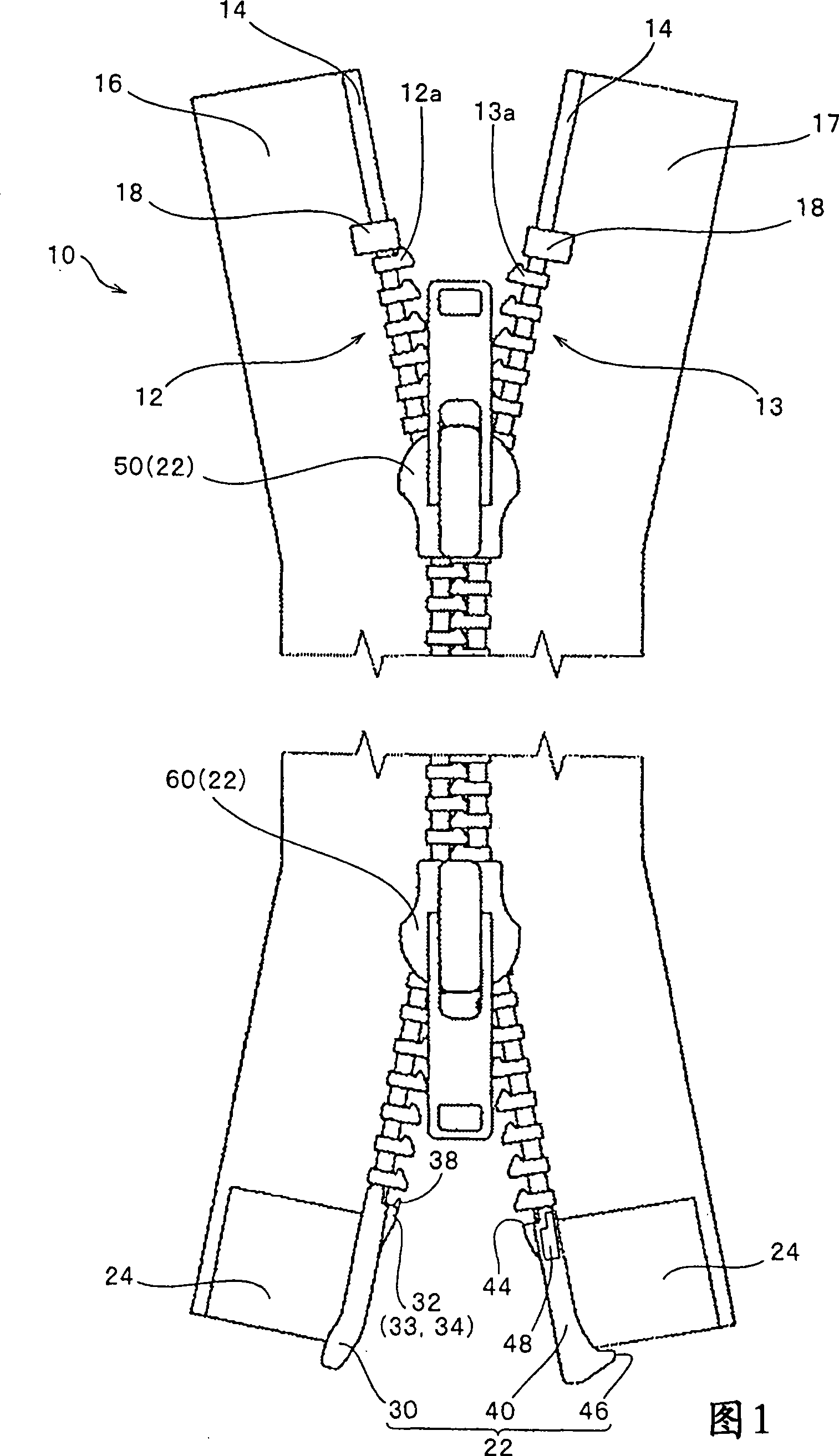
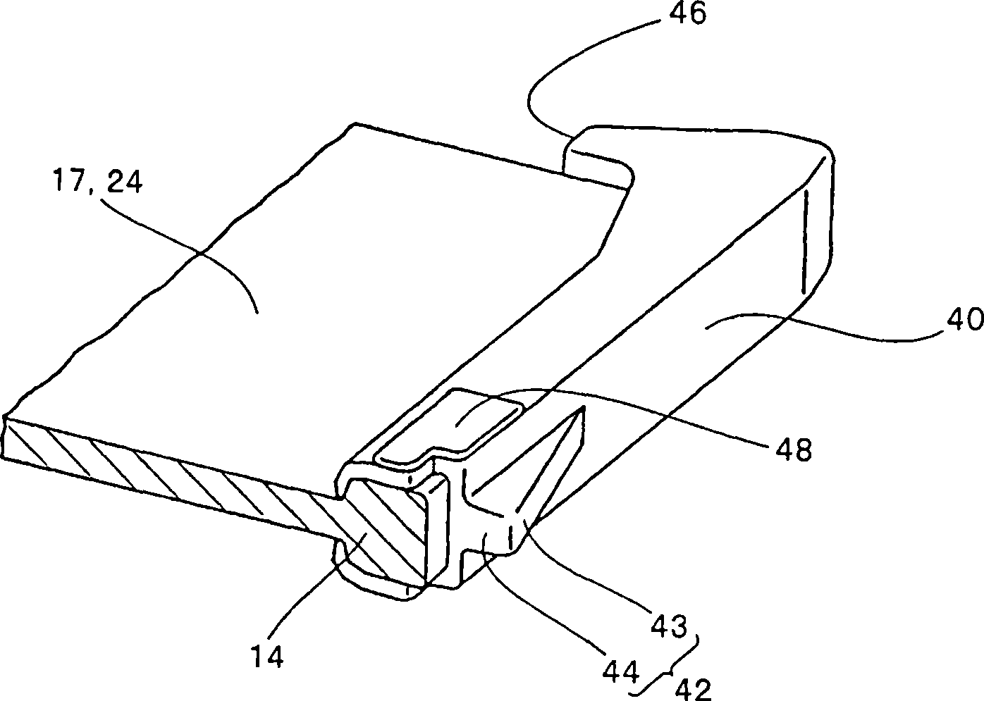
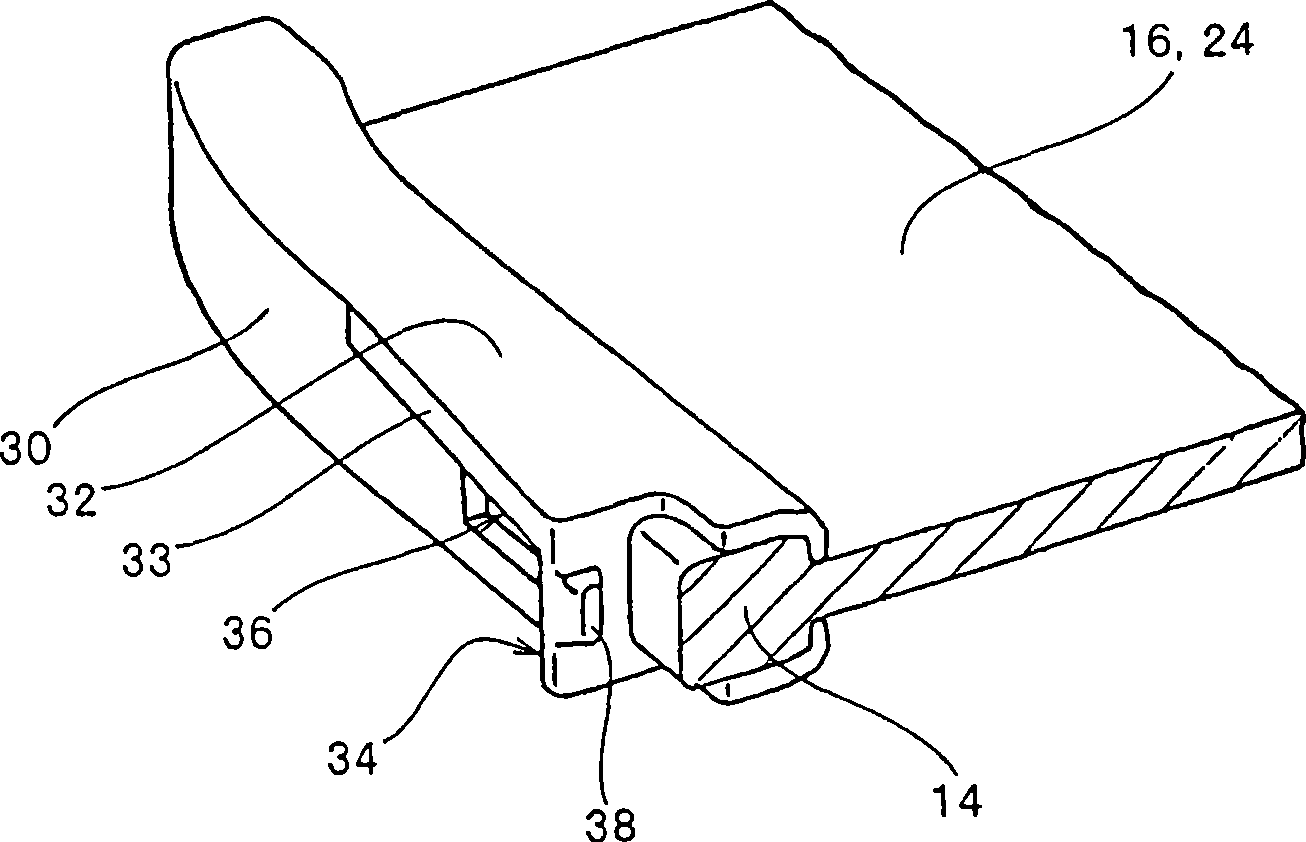
[0037] FIG. 1 is an external view of the entire anti-opening zipper 10, or shows that the upper slider 50 is slightly lowered from the contact position of the upper stops 18, 18 while the lower slider 60 is slightly raised from the insertion position of the insertion tube 30 and the seat tube 40. In the front view of the state, the insertion tube 30 and the seat tube 40 are detachable bottom stops. figure 2 is a partial perspective view showing, in a partially cutaway state, a portion adjacent to the seat tube mounting end of the right fastener stringer 17 (first fastener stringer) having the continuously disposed seat tube 40; and image 3 It is a partial perspective view showing, in a partially cutaway state, a portion adjacent to the cannula connection end of the left fastener stringer 16 (second fastener stringer) having the cannula 30 disposed continuously.
[0038] As shown in FIG. 1 , the reverse slide fastener 10 is an opening / closing device capable of opening or closi...
no. 2 example
[0070] Next, other embodiments regarding the arrangement of the protruding portion formed on the side of the seat tube will be described.
[0071] 8 is a diagram showing that a protruding portion 48, which is a characteristic part of the present invention, is formed on the front side (surface side of the same drawing) of the upper portion of the seat tube 140 and that a protruding portion 149 is also formed on the front side (the same drawing) of the center portion of the seat tube 140. The cross-sectional view of the state on the surface side of the figure). FIG. 8 is a view showing a state where the upper slider 50 and the lower slider 160 are pulled to the lowest positions so as to completely pull out the cannula 30 . At the same time, the same reference numerals are assigned to perform as Image 6 Components and parts having the same functions as in , and descriptions thereof are omitted.
[0072] As shown in FIG. 8, at the upper portion of the seat tube 140, a protrudin...
no. 3 example
[0075] Next, other embodiments regarding the shape of the protruding portion formed on the side of the seat tube will be described.
[0076] Figure 9 is a perspective view showing an example in which oval protrusions 248 are formed on the front and rear sides of the upper portion of the seat tube 240 . At the same time, the same reference numerals are assigned to perform as figure 2 Components and parts having the same function as in , and their descriptions are omitted.
[0077] Such as Figure 9 As shown in , a plurality of oval protrusions 248 are formed on the front side of the seat tube 240 opposite to the inner surface (see FIG. 7 ) of the front plate 52 of the upper slider 50 so that when the upper slider 50 is pulled down to the lowest position The state prevents free sliding of the upper slider 50 because the seat tube 240 is in contact with the inner surface of the front plate 52 at various locations.
[0078] If the oval protruding portion 248 is disposed on th...
PUM
 Abstract
Description
Claims
Application Information
 - R&D
- Intellectual Property
- Life Sciences
- Materials
- Tech Scout
- Unparalleled Data Quality
- Higher Quality Content
- 60% Fewer Hallucinations
Browse by: Latest US Patents, China's latest patents, Technical Efficacy Thesaurus, Application Domain, Technology Topic, Popular Technical Reports.
© 2025 PatSnap. All rights reserved.Legal|Privacy policy|Modern Slavery Act Transparency Statement|Sitemap|About US| Contact US: help@patsnap.com


