
Multifunctional optical fiber grating sensing system

A fiber grating and sensing system technology, applied in the direction of using optical devices to transmit sensing components, can solve the problems of slow test speed, high cost and high cost of multi-parameter sensing systems, and achieve the elimination of measurement errors and mature technology. The effect of fast demodulation speed

Inactive Publication Date: 2010-06-16
DONGHUA UNIV
View PDF5 Cites 0 Cited by
  • Summary
  • Abstract
  • Description
  • Claims
  • Application Information

AI Technical Summary

Problems solved by technology

In the above demodulation methods, the measurement range of interferometric demodulation is limited by the free spectral range of the interferometer; the tunable light source is difficult to manufacture and the cost is high; the scan period of the tunable filter is long, the test speed is slow, and the repeatability is poor; the matching The demodulation range of the filter is too small
Due to the existence of the above shortcomings, wavelength demodulation technology has become one of the main obstacles to the industrialization of FBG sensing technology
[0017] In a common fiber grating sensing system, the sensing element only has a sensing function, and the demodulation element only has a demodulation function, so the cost of a multi-parameter sensing system is usually very high

Method used


Image

  • Multifunctional optical fiber grating sensing system
  • Multifunctional optical fiber grating sensing system
  • Multifunctional optical fiber grating sensing system

Examples


Embodiment Construction

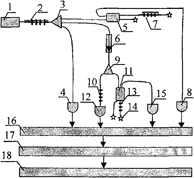
[0034] Below in conjunction with specific embodiment, further illustrate the present invention. It should be understood that these examples are only used to illustrate the present invention and are not intended to limit the scope of the present invention. In addition, it should be understood that after reading the teachings of the present invention, those skilled in the art can make various changes or modifications to the present invention, and these equivalent forms also fall within the scope defined by the appended claims of the present application.

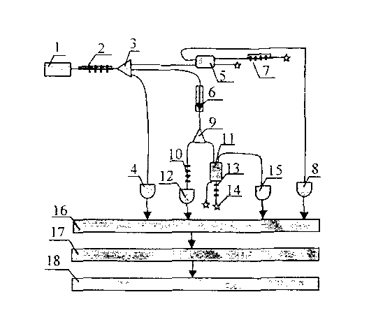
[0035] Such as figure 1 As shown, the strain, temperature, pressure, vibration and other multifunctional sensing systems realized by the present invention are characterized in that the output light of the broadband light source 1 enters the first beam splitter 3 after being modulated by the long-period fiber grating 2; Then respectively enter the first optical coupler 5, optical isolator 6 and first photodetector 4; the output...


PUM


Abstract

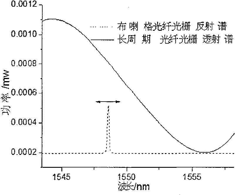
The invention relates to a multifunctional fiber grating sensing system. Output light of a broadband light source enters a beam splitter after being modulated by a long-period fiber gating, and the split beams respectively enter an optical coupler, an optical isolator and a photo detector. The emergent light from the coupler enters a first fiber Bragg grating; the emergent light from the optical isolator enters another beam splitter, and the emergent light from the beam splitter is divided into two parts, the first part enters a second fiber Bragg grating, and the second part enters a third fiber Bragg grating through a second coupler; the light reflected / transmitted by the three fiber Bragg gratings is received by a corresponding photo detector, and all output signals of the photo detectors are acquired by a data acquisition card and processed by a computer. The fiber grating sensing system has the function of measuring a plurality of different parameters, the function of automatically eliminating measurement errors caused by fluctuation of output power of the light source, and the function of automatically eliminating the measurement errors caused by change of the ambient temperature.

Description

technical field [0001] The invention belongs to the technical field of optical fiber grating sensing, and in particular relates to a multifunctional optical fiber grating sensing system with the functions of measuring various parameters, automatically eliminating the main error of the system, and self-demodulating. Background technique [0002] A fiber grating is an optical element that establishes a certain spatial refractive index periodic distribution in an optical fiber, so that the propagation characteristics of light can be changed in it. [0003] When broadband light is incident on a fiber Bragg grating (hereinafter referred to as FBG), the central wavelength (Bragg wavelength) λ of the reflected light is B is given by the Bragg equation: λ B =2nΛ [0004] Among them, n is the effective refractive index of the fiber core, and Λ is the grating period. [0005] When physical quantities such as the strain of FBG and the ambient temperature change, it will cause λ B C...

Claims


Application Information

Patent Timeline
Patent Type & Authority Patents(China)
IPC IPC(8): G01D5/26
Inventor 詹亚歌闫向阳詹哈克
Owner DONGHUA UNIV
Learn More